Direct-drive electro-hydraulic actuator

A technology for driving electricity and actuators, which is applied to fluid pressure actuators, fluid pressure actuator system components, mechanical equipment, etc. It can solve problems such as low reliability, inability to eliminate, and vibration of oil pipelines to improve work performance , high flexibility, high reliability effect

Active Publication Date: 2012-07-18
BEIHANG UNIV
View PDF6 Cites 31 Cited by
  • Summary
  • Abstract
  • Description
  • Claims
  • Application Information

AI Technical Summary

Problems solved by technology

When adjusting the speed of the motor, the motor mover plus the rotating parts on the plunger pump, the total moment of inertia is a big burden for the high-speed, low-torque motor, so the frequency response of the speed regulation is limited; When adjusting the swash plate variable mechanism, due to the many transmission parts of the swash plate mechanism, the structure is complicated, and the control performance is not ideal
[0006] (3) The plungers in the axial plunger pump are structurally cross-linked and coupled. During the uniform rotation of the cylinder, due to the difference in movement of each plunger pump, the overall output flow of the pump fluctuates. This pulsation is The inherent properties of the plunger pump cannot be eliminated, and the vibration of the oil pipeline caused by the pulsation of the pump source is a major problem in the hydraulic system.
[0007] (4) Although a plunger pump has multiple plungers working in a cycle to provide energy for the system together, when one of the plungers fails, due to the structural connection, it will inevitably affect other plungers, and A fatal failure of a single plunger will inevitably make the entire system unable to work. If the plunger pump is backed up with double redundancy, the volume and weight of the system will be greatly increased.
Therefore, the electrostatic hydraulic actuator composed of a plunger pump has relatively low reliability due to the configuration of single redundancy

Method used


Image

  • Direct-drive electro-hydraulic actuator
  • Direct-drive electro-hydraulic actuator
  • Direct-drive electro-hydraulic actuator

Examples


Embodiment Construction

[0035] The present invention will be further described in detail with reference to the accompanying drawings and embodiments.

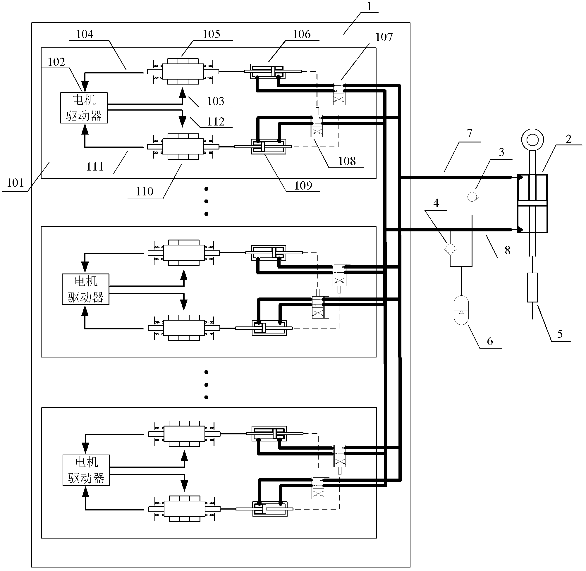
[0036] The present invention is a direct drive electrohydrostatic actuator, such as figure 2 As shown, it includes a direct drive electro-hydraulic servo pump 1, a pressurized oil tank 6, a first oil supply check valve 3, a second oil supply check valve 4, and a hydraulic cylinder 2, and its core component is a direct drive electro-hydraulic servo pump 1 .

[0037] The direct drive electro-hydraulic servo pump 1 includes a plurality of oil supply modules 101, and each oil supply module 101 has the same structure; the oil supply module 101 includes a motor driver 102, a first linear oscillating motor 105, a second linear oscillating motor 110, The first oil suction and discharge piston 106 , the second oil suction and discharge piston 109 , the first distribution valve 107 and the second distribution valve 108 .

[0038] The motor driver 102 receive...


PUM


Abstract

The invention discloses a direct-drive electro-hydraulic actuator which comprises a direct-drive electro-hydraulic servo pump, a pressurizing oil tank, a first oil compensation check valve, a second oil compensation check valve and a hydraulic cylinder; according to the direct-drive electro-hydraulic actuator, a plurality of oil supply units are combined for use, so that the direct-drive electro-hydraulic servo pump system can be combined for construction according to the power requirement of an integrated hydraulic system; and parts do not need to be designed independently, so that the system has higher flexibility. According to the direct-drive electro-hydraulic actuator, the plurality of oil supply units work simultaneously so as to form a heat backup of the direct-drive electro-hydraulic servo pump system, particularly, redundant configuration is carried out to the pump system; when one or a quantity of oil supply units fail, the other oil supply units can lead the pump system to degrade to work, and compared with the condition that the whole pump fails when a plunger of an axial plunger pump is pulled away or tightly clamped, the direct-drive electro-hydraulic servo pump system has higher reliability.

Description

technical field [0001] The present invention relates to an electrostatic fluid actuator, more particularly, to a direct-drive electrostatic fluid actuator. Background technique [0002] The traditional hydraulic system generally uses a central hydraulic pump source to transmit energy to each actuating system. In a system that is relatively large and complex and has multi-terminal distributed actuators, the layout of the pipeline will become a huge burden. The resulting cost increase, increased leakage, and pipeline vibration have plagued the development of distributed hydraulic systems. The emergence of power-by-wire actuators has solved these problems very well. It transmits energy in the form of unified electric energy, converts the form of energy locally in the actuator, and drives and transmits through a certain structural form. This point is more obvious in the application of the control system of the aircraft. At present, the Airbus A380 and other models have realized...

Claims


Application Information

Patent Timeline
Patent Type & Authority Applications(China)
IPC IPC(8): F15B15/18F15B21/08
Inventor 焦宗夏李洋严亮尚耀星吴帅黄澄梁惠升
Owner BEIHANG UNIV
Why Eureka
Try Eureka