Electric hydraulic servo clutch and corresponding gear box and vehicle
A hydraulic servo and clutch technology, applied in the clutch field, can solve the problems of inaccurate stroke position control, complex clutch control structure, increased cost and space, etc., and achieve the effects of simple control method, simple structure and long service life
- Summary
- Abstract
- Description
- Claims
- Application Information
AI Technical Summary
Problems solved by technology
Method used
Image

Examples
Embodiment Construction
[0028] The content of the present invention will be described below in conjunction with the accompanying drawings. The following description is only exemplary and explanatory, and should not have any limiting effect on the protection scope of the present invention.
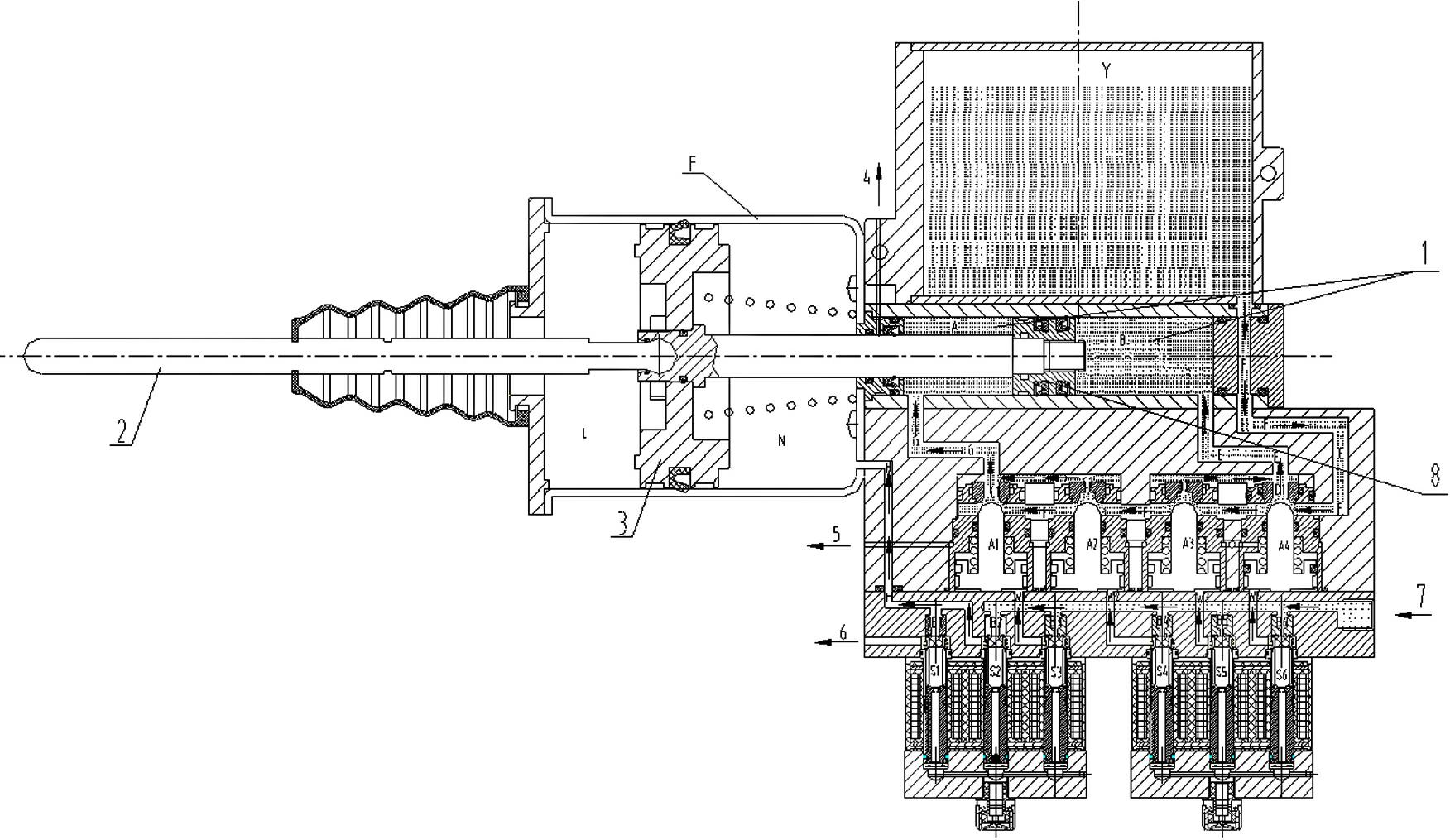
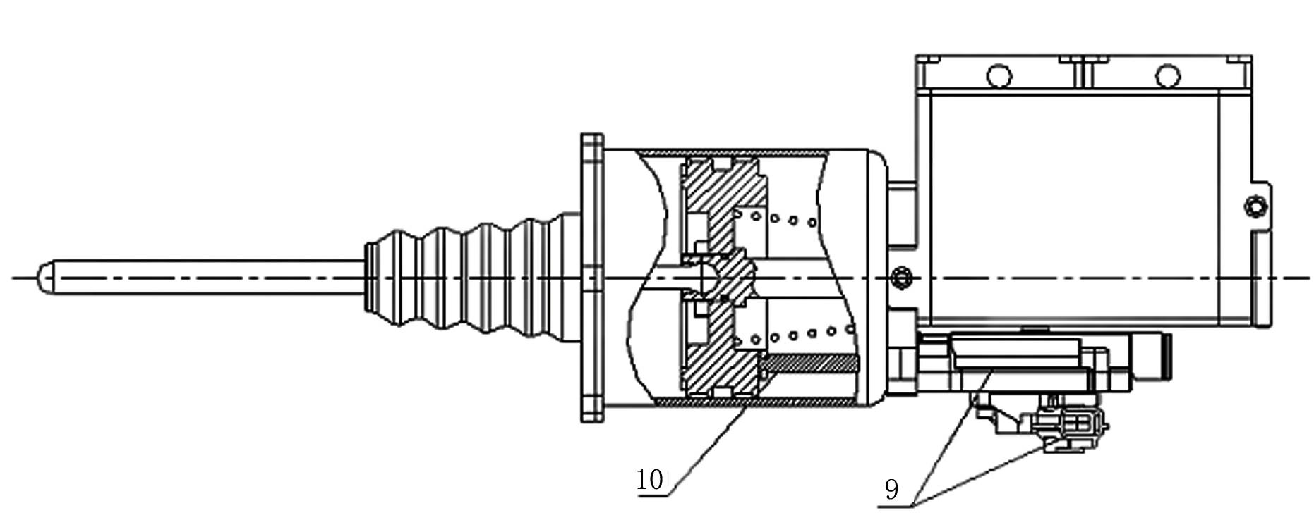
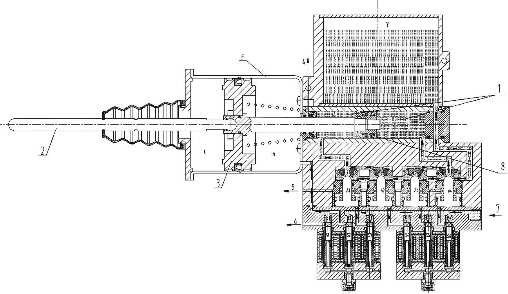
[0029] An electro-hydraulic servo clutch, including a hydraulic working chamber 1, a push rod 2, a booster piston 3, a breathing hole 4, a breathing hole 5, an exhaust port 6, an air inlet 7, an oil pot Y, a hydraulic piston 8, and a stroke sensor 9 , the sensor connecting rod 10 also includes the control piston A1, the control piston A2, the control piston A3, and the control piston A4. In the hydraulic chamber A, the end of the large pneumatic piston A is set in the hydraulic chamber B, wherein the hydraulic chamber A and the hydraulic chamber B are separated by the hydraulic piston and the sealing device. The force of the hydraulic working chamber 1 is equal to the working chamber N of the booster cylinder. Th...
PUM
 Abstract
Description
Claims
Application Information
 - R&D
- Intellectual Property
- Life Sciences
- Materials
- Tech Scout
- Unparalleled Data Quality
- Higher Quality Content
- 60% Fewer Hallucinations
Browse by: Latest US Patents, China's latest patents, Technical Efficacy Thesaurus, Application Domain, Technology Topic, Popular Technical Reports.
© 2025 PatSnap. All rights reserved.Legal|Privacy policy|Modern Slavery Act Transparency Statement|Sitemap|About US| Contact US: help@patsnap.com