Parallel confocal detection system and method

A detection system and detection method technology, applied in the field of confocal imaging, can solve problems that affect measurement accuracy and cannot achieve flexible measurement, and achieve the effects of increasing scanning speed, realizing flexible measurement, and solving mechanical vibration

Inactive Publication Date: 2012-07-18
UNIV OF SHANGHAI FOR SCI & TECH
View PDF3 Cites 9 Cited by
  • Summary
  • Abstract
  • Description
  • Claims
  • Application Information

AI Technical Summary

Problems solved by technology

However, due to the introduction of mechanical rotation, the measurement accuracy is greatly affected
The parallel transverse scanning technology mainly includes Nipkow disk and microlens array, which can solve the problem of single-point confocal microscope, but the optical parameters of Nipkow disk and microlens array are determined after they are fabricated, and flexible measurement cannot be realized.

Method used


Image

  • Parallel confocal detection system and method
  • Parallel confocal detection system and method

Examples


Embodiment 1

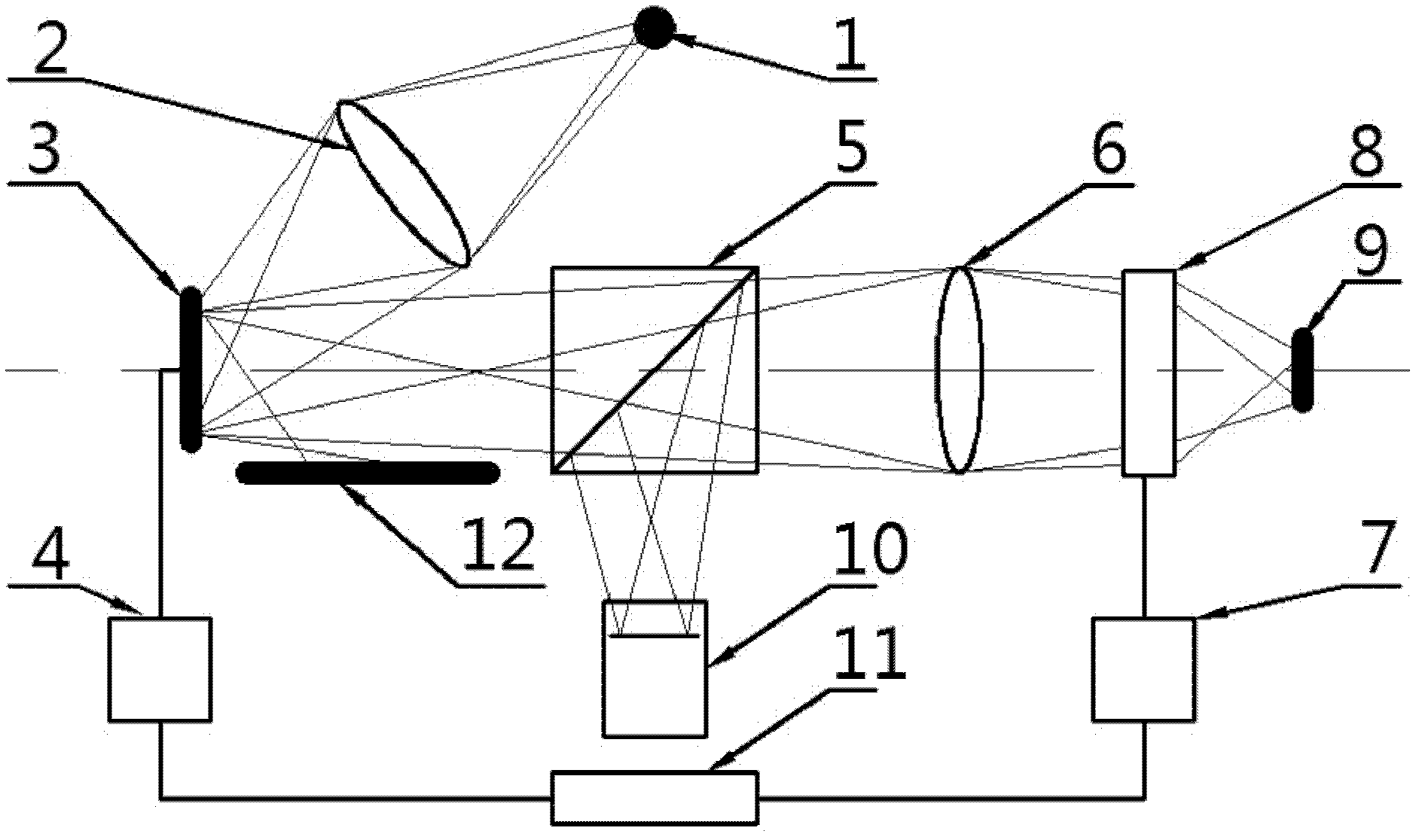
[0021] see figure 1 , the present invention discloses a parallel confocal detection system, said system comprising: a monochromatic LED light source 1, a condenser lens 2, a digital micromirror 3, a control board 4, two lenses 6, a beam splitter 5, an electronically controlled variable focus lens 8. Detection pinhole, light intensity detector 10, voltage controller 7, PC11, absorption plate 12.

[0022] The light emitted by the monochromatic LED light source 1 is irradiated onto the surface of the digital micromirror DMD 3 through the condenser lens 2, and the digital micromirror DMD 3 is modulated by the control board 4 to form a pinhole array, and first passes through the non-polarization beam splitter 5, (parts do not pass through The light of the beam splitter 5 is absorbed by the absorbing plate 12, which does not affect the received light intensity of the light intensity array detector CCD / CMOS 10) and then passes through the lens barrel lens 6 to become a parallel light...

Embodiment 2

[0026] A parallel confocal detection method of the above-mentioned parallel confocal detection system, the method specifically includes the following steps:

[0027] 1) The light emitted by the monochromatic LED light source is irradiated to the surface of the digital micromirror through the light collecting mirror. The light source is modulated by the digital micromirror to form a pinhole array, and then becomes a parallel beam through the lens. The zoom lens, the focused surface of the measured object, the light reflected by the measured object passes through the zoom lens, the beam splitter, and the lens detection pinhole, and is incident on the light intensity array detector, and the light intensity is recorded by the PC;

[0028] 2) The PC controls the voltage applied to the electronically controlled variable focus lens through the voltage controller, so that the focal length of the variable focus lens is changed by a small value Δf, and Δf is less than 1um. At this time, ...


PUM


Abstract

The invention discloses a parallel confocal detection system and a parallel confocal detection method. The system comprises a mono-color LED (light-emitting diode) light source, a digital micro-lens, two lenses, a beam splitter prism, an electric-control variable focal length lens, a detection pinhole, a light strength detector, a voltage controller and a PC (personnel computer). Lights sent out by the mono-color LED light source are irradiated on the surface of the digital micro-lens through a light collection lens and a light source is modulated by the digital micro-lens to form a pinhole array; the lights are changed into a parallel light beam by the lens to be focused on the surface of an object to be detected; the lights reflected by the object to be detected are emitted into a light strength array detector; and a sample is transversely or axially scanned through a digital micro-lens device. A voltage on the electric-control variable focal length lens is controlled by the PC to change a focal length of the variable focal length lens for a tiny value delta f, and a light strength numerical value on the detector is recorded; the axial position of the corresponding point of the object to be detected is obtained according to the light strength value obtained by scanning; and the surface outline of the whole object to be detected is measured. According to the parallel confocal detection system and parallel confocal detection method, the stability and the scanning speed of the system can be improved.

Description

technical field [0001] The invention belongs to the technical field of confocal imaging, and relates to a confocal detection system, in particular to a parallel confocal detection system; meanwhile, the invention also relates to a parallel confocal detection method of the parallel confocal detection system. Background technique [0002] In 1957, M.Minsky, a postdoctoral fellow at Harvard University, proposed the concept of confocal imaging for the first time. The purpose was to eliminate the various scattered lights produced by ordinary optical microscopes when detecting samples. For this reason, he proposed a new imaging model - confocal imaging. In this imaging model, a point light source is introduced and imaged on the surface of the measured object, and the light reflected by the measured object is received by a very small light intensity detector (which can be regarded as a point detector). When the point light source, the measured object and the point detector are con...

Claims


Application Information

Patent Timeline
Patent Type & Authority Applications(China)
IPC IPC(8): G01B11/24
Inventor 张运波杨召雷句爱松彭博方董洪波胡凯侯文玫
Owner UNIV OF SHANGHAI FOR SCI & TECH
Why Eureka
Try Eureka