Optical fiber ring packaging structure applicable to medium/high-precision optical fiber inertia unit

A packaging structure, fiber ring technology, applied in installation, optics, measurement devices, etc., can solve the problems of uneven temperature distribution of the fiber ring, fiber optic gyro bias error, fiber optic gyro output error, etc., to achieve good air tightness, easy to use. The effect of machining and assembly, good vibration resistance

Active Publication Date: 2014-12-03
BEIHANG UNIV
View PDF10 Cites 0 Cited by
  • Summary
  • Abstract
  • Description
  • Claims
  • Application Information

AI Technical Summary

Problems solved by technology

At the same time, the external temperature change and the thermal design of the gyro itself will also cause the temperature distribution inside the fiber optic ring to be uneven, resulting in "non-reciprocity" phase shift, resulting in the output error of the fiber optic gyroscope; secondly, the fiber optic ring as a sensitive element, under different pressure Under these conditions, internal anisotropic stress will be generated, which will cause stress birefringence through the photoelastic effect, and then cause bias error; in addition, the sensitivity of the bias magnetic field is another important parameter of the fiber optic gyroscope, and the influence of the external magnetic field on the fiber optic gyroscope is mainly It is the magneto-induced Farady effect. The Farady effect changes the refractive index of the optical fiber, affects the optical path difference of the light in the forward and reverse directions, and produces a non-reciprocal effect, which causes the bias error of the fiber optic gyroscope.

Method used


Image

  • Optical fiber ring packaging structure applicable to medium/high-precision optical fiber inertia unit
  • Optical fiber ring packaging structure applicable to medium/high-precision optical fiber inertia unit
  • Optical fiber ring packaging structure applicable to medium/high-precision optical fiber inertia unit

Examples


Embodiment Construction

[0024] The present invention will be further described below in conjunction with the accompanying drawings.

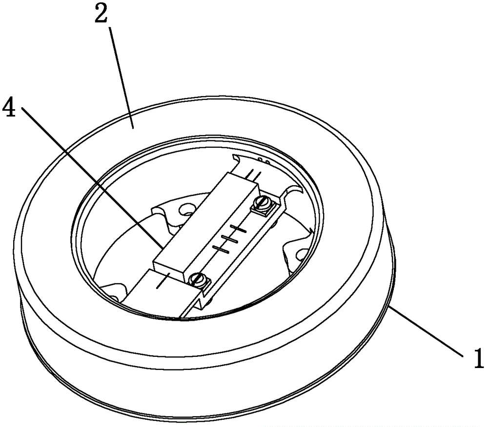
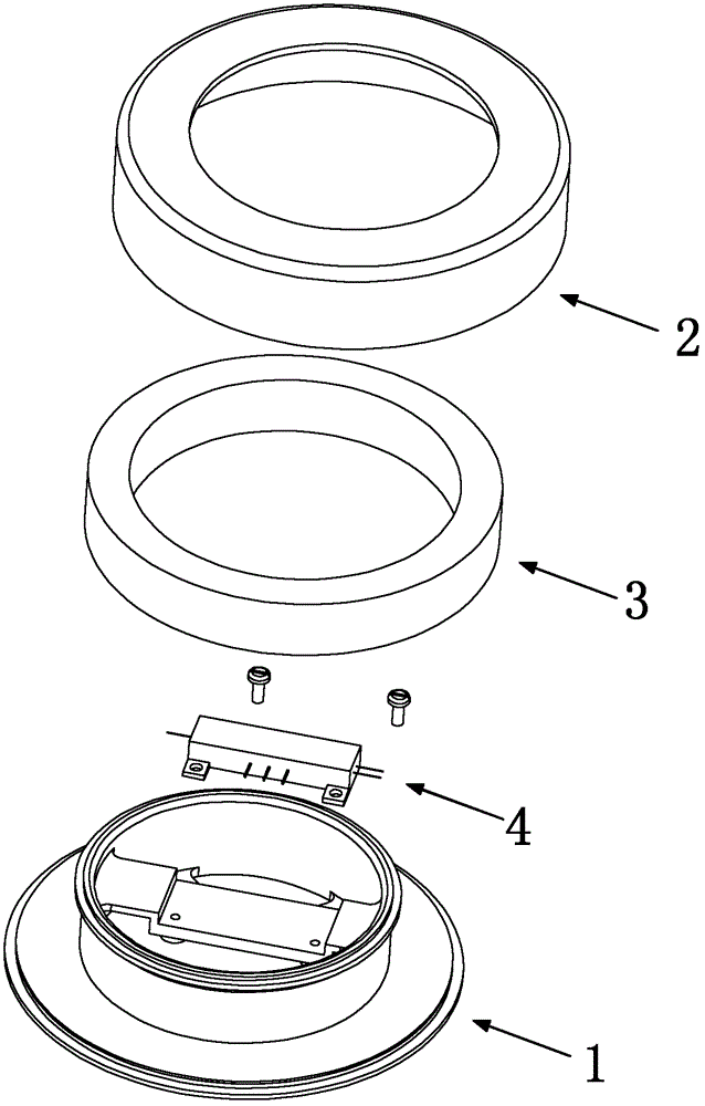
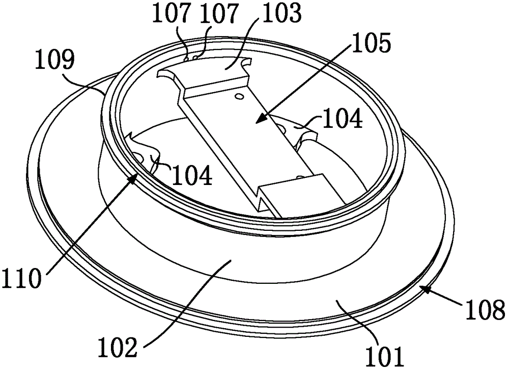
[0025] The optical fiber ring packaging structure of the present invention includes a support body 1 and a cover 2, such as figure 1 , figure 2 shown. Wherein, the support body 1 is an integral structure composed of an annular chassis 101, a sleeve 102, a Y waveguide installation beam 103 and an installation surface 104, as shown in image 3 As shown, the inner circumference of the annular chassis 101 is connected to the bottom end of the sleeve 102 in the circumferential direction, and the annular chassis 101 and the sleeve 102 are used to place and position the optical fiber ring 3 respectively. The Y-waveguide installation crossbeam 103 is arranged on the inner side wall of the sleeve 102, and the middle part of the upper surface of the Y-waveguide installation crossbeam 103 is concaved to form a Y-waveguide installation groove 105, and the Y-waveguide 4 is fixed...


PUM


Abstract

The invention discloses an optical fiber ring packaging structure applicable to a medium / high-precision optical fiber inertia unit. The optical fiber ring packaging structure comprises a supporting body, a sealing cover, an optical fiber ring and a Y waveguide, wherein the supporting body has an integral structure consisting of an annular base plate, a sleeve, a Y waveguide mounting transverse beam and a mounting surface; an inner circumference of the annular base plate is connected with the bottom end of the sleeve in a circumferential direction, the optical fiber ring is sleeved on the sleeve, and the bottom surface is adhered to the annular base plate; the Y waveguide mounting transverse beam is arranged on an inner side wall of the sleeve, and a Y waveguide mounting groove is formed on the Y waveguide mounting transverse beam; and optical fiber outlet holes are formed on the inner wall of the sleeve in the supporting body, and two tail fibers at two ends of the optical fiber ring pass through the optical fiber outlet holes to be fused with two tail fibers at one end of the Y waveguide respectively. The annular sealing cover is fixedly connected with the supporting body, so that the optical fiber ring is sealed between the sealing cover and the supporting body. The invention has the advantages that the optical fiber ring packaging structure has a simple structure, a modular integral structure, compact device layout, high vibration resistance, high air impermeability and high thermal insulation and is easy to machine and assemble.

Description

technical field [0001] The invention relates to an optical fiber ring packaging structure suitable for medium and high-precision optical fiber inertial groups. Specifically, it is a structure for carrying and packaging the optical fiber ring of the main sensitive device of the optical fiber gyroscope by using magnetic shielding materials and welding methods. Background technique [0002] The inertial navigation system based on fiber optic gyroscope is an autonomous navigation system developed in the last century. The fiber optic gyroscope is used to sense the rotation information of the carrier relative to the inertial system, and the accelerometer mainly measures the linear motion information of the carrier relative to the inertial space. As a new generation of important inertial technology, fiber optic gyroscope has the advantages of full solid state, high reliability, large dynamic range, small size, etc. At present, it is constantly developing from medium and low precisio...

Claims


Application Information

Patent Timeline
Patent Type & Authority Patents(China)
IPC IPC(8): G01C25/00G01C19/72G02B7/00
Inventor 刘海霞徐宏杰章博宋凝芳
Owner BEIHANG UNIV
Why Eureka
Try Eureka