Moisture detecting method for overheated steam of steam pipeline of turbine

A technology for detecting sensors and steam pipelines, which is applied in the direction of material analysis, instruments, and measuring devices by optical means, can solve the problems of safety, failure to monitor the moisture of superheated steam, hidden dangers, etc., and achieves low production cost and separation of steam and water. Good effect and easy installation effect

Inactive Publication Date: 2013-10-23
杨英杰
View PDF7 Cites 0 Cited by
  • Summary
  • Abstract
  • Description
  • Claims
  • Application Information

AI Technical Summary

Problems solved by technology

[0003] The purpose of the present invention is to solve the problem that the superheated steam moisture in the steam turbine steam pipeline cannot be monitored during the operation of the power plant and the nuclear power plant, and there are potential safety hazards, and further provide a steam turbine steam pipeline superheated steam moisture detection sensor

Method used


Image

  • Moisture detecting method for overheated steam of steam pipeline of turbine
  • Moisture detecting method for overheated steam of steam pipeline of turbine
  • Moisture detecting method for overheated steam of steam pipeline of turbine

Examples


specific Embodiment approach 1

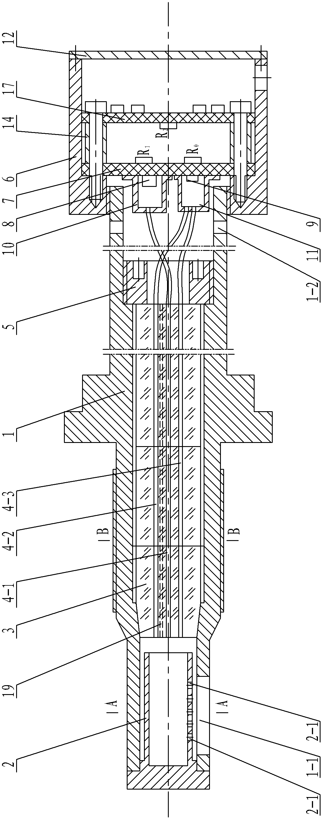
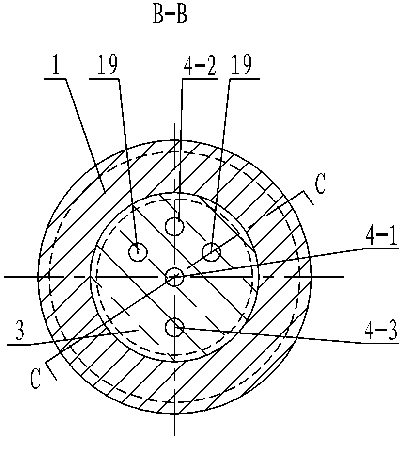
[0009] Specific implementation mode one: combine Figure 1 to Figure 7 Describe this embodiment, the steam turbine steam pipeline superheated steam moisture detection sensor of this embodiment includes a circular tubular shell 1, a short pipe 2, an insulating cylinder 3, a first optical fiber 4-1, a second optical fiber 4-2, and a third optical fiber 4 -3, wire ring 5, cylindrical metal box 6, front insulating plate 7, light-emitting diode 8, photocell 9, first metal cover 10, second metal cover 11, box cover 12, rear insulating plate 17, measuring resistance R 0 , compensation resistor R 1 , adjustable resistance R 2 , the first pair of terminals 16 and the second pair of terminals 18;

[0010] The short tube 2 is a short tube with one end closed, the open section of the short tube 2 is inserted into the front end of the round tubular shell 1, the closed end of the short tube 2 is fixedly connected with the round tubular shell 1, and the inner end surface of the closed end ...

specific Embodiment approach 2

[0014] Specific implementation mode two: combination figure 1 This embodiment will be described. The short pipe 2 of this embodiment is made of stainless steel. So set, the service life is longer. Other components and connections are the same as those in the first embodiment.

specific Embodiment approach 3

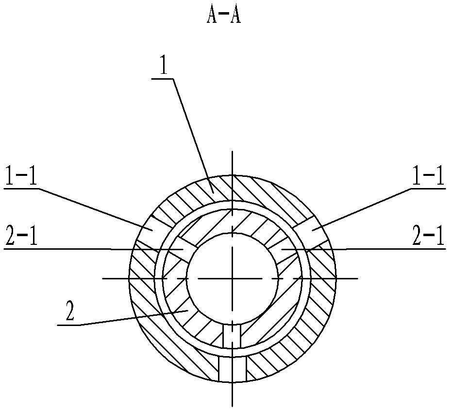
[0015] Specific implementation mode three: combination figure 1 and figure 2 To illustrate this embodiment, each exhaust hole 2-1 of this embodiment includes 5 small holes, the diameter of which is 4 mm, and the center distance between the holes is 8 mm. With such setting, the separation effect of soda and water is better. Other compositions and connections are the same as those in Embodiment 1 or Embodiment 2.


PUM

PropertyMeasurementUnit
surface roughnessaaaaaaaaaa
pore sizeaaaaaaaaaa
diameteraaaaaaaaaa

Abstract

The invention relates to a moisture detecting method for overheated steam of a steam pipeline of a turbine, which aims at solving the problems that the steam pipeline of the turbine is not protected during operation of a power station and a nuclear power station, and potential safety hazards still exist. A steam sampling unit is arranged on the front portion of the sensor, a signal transmission unit is arranged in the middle of the sensor, a detecting unit is arranged on the rear portion of the sensor. A short pipe is inserted into the front end of a round tube casing, an end face of a sealing end of the short pipe is smooth and clean, holes are arranged on the short pipe and a round pipe casing, an insulation column body is arranged in the middle of the round pipe casing, an optical fiber inserting hole is arranged on the insulation column body, an optical fiber is inserted into the optical fiber inserting hole to be bonded with a hole wall, a front insulation plate and a rear insulation plate are installed in a cylindrical metal box, a light-emitting diode and a photocell are arranged on the front end face of the front insulation plate and packaged on the front insulation plate through a metal cover, and a connecting hole bonded with the optical fiber is arranged at the front end of the metal cover. The moisture detecting method is used for detecting whether water exists in the steam pipeline of the turbine.

Description

technical field [0001] The invention relates to a sensor for detecting superheated steam moisture in a steam pipeline, in particular to a sensor for detecting superheated steam moisture in a steam pipeline of a steam turbine. Background technique [0002] For steam turbines in normal operation (except for start-up and shutdown processes), the pressure and temperature of the steam are operated according to the design parameters, and there are strict regulations on the rate of change of the steam temperature. Absolutely no moisture is allowed in the superheated steam. The moisture contained in the superheated steam caused severe damage to the steam turbine, including burnt bearing bushes, worn impellers, broken blades, and bent shafts. The strong vibration will cause great damage to the unit, which may cause damage to the oil passage system of the unit, turbine oil ejection, fire, and hydrogen system explosion of the generator. Water entering the steam turbine not only damag...

Claims


Application Information

Patent Timeline
Patent Type & Authority Patents(China)
IPC IPC(8): G01N21/17
Inventor 杨英杰杨英姿杨卓清刘雅琴
Owner 杨英杰
Why Eureka
Try Eureka