Supercharge Your Innovation With Domain-Expert AI Agents!

Developing unit based on display module and electronic photograph imaging device

A technology of display module and developing device, which is applied to the equipment of the electric recording process using the charge pattern, the electric recording process using the charge pattern, and the electric recording technique, etc., which can solve the problem of poor LED light directionality and printing axial resolution Low, high failure rate of light source and other problems, to achieve the effect of simple structure, high imaging efficiency and simple technology

Inactive Publication Date: 2012-07-18
李华容
View PDF0 Cites 2 Cited by
  • Summary
  • Abstract
  • Description
  • Claims
  • Application Information

AI Technical Summary

Problems solved by technology

[0007] To sum up, the exposure device and the photosensitive device of all current electrophotographic imaging equipment are separated, and the light source of the exposure device is either a laser or an LED (or OLED) array, which is located outside the photosensitive device. A row (that is, a horizontal array) of photosensitive points of the photosensitive device is photosensitive, and its printing speed depends not only on the rotation speed of the photosensitive device, but also on the exposure speed of the exposure device, so the current electrophotographic imaging speed is not as fast as that of industrial printing machines.
Moreover, laser scanning printers will have problems such as high light source failure rate, large machine volume, harmful gas generation, and blurred edges of printed images. Although LED (or OLED) array printers solve the above technical problems and print faster It has also been relatively improved, but there are still low printing axial resolution and poor directivity of LED light, and serious scattering. If the mutual interference between LED (or OLED) arrays is not handled well, the printed image will appear Deviation, so the requirements for the imaging optical system are stricter and the cost is higher

Method used


Image

  • Developing unit based on display module and electronic photograph imaging device
  • Developing unit based on display module and electronic photograph imaging device
  • Developing unit based on display module and electronic photograph imaging device

Examples


Embodiment 1

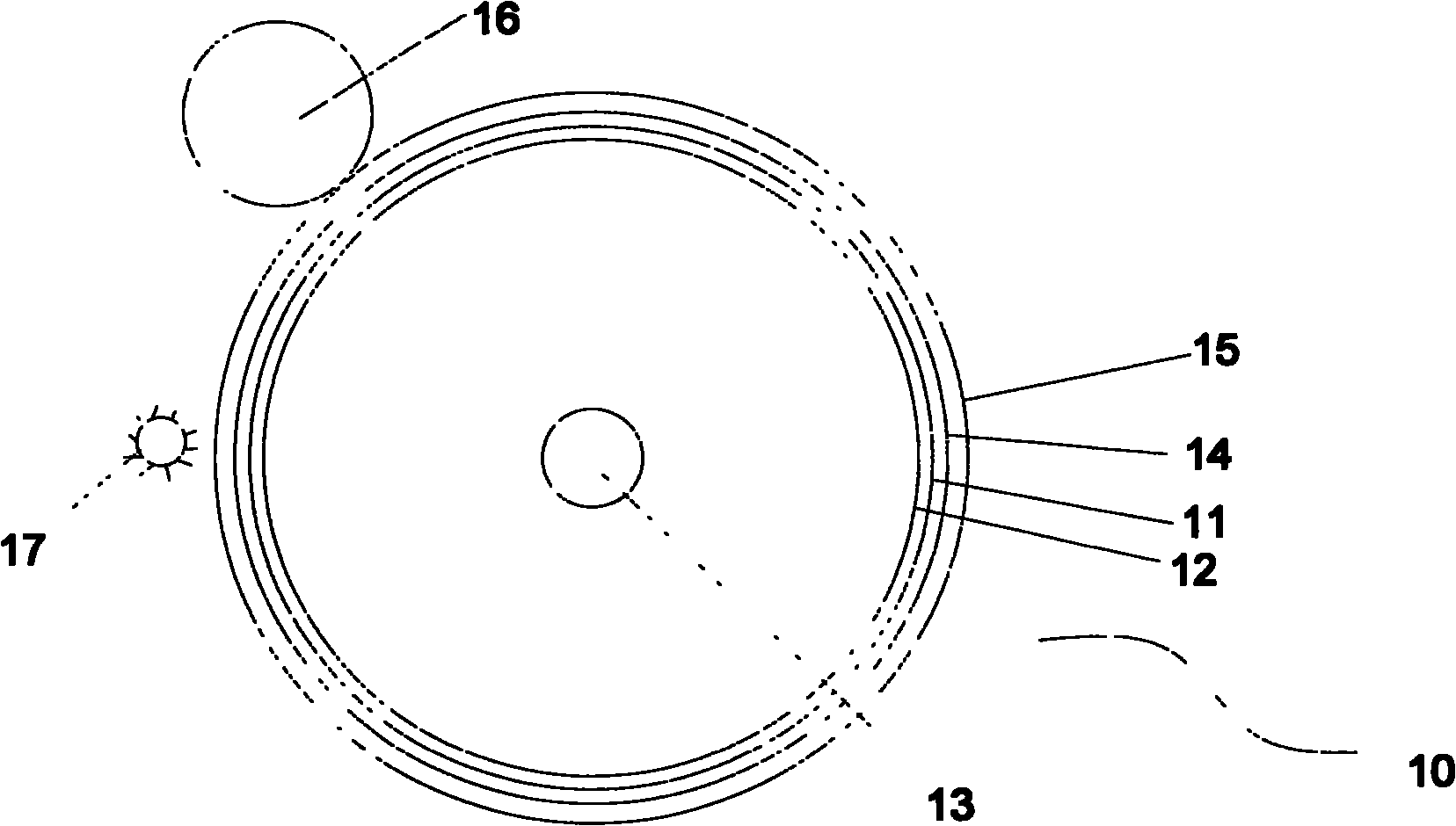
[0053] This embodiment provides a developing device 10, such as Figure 1-2 As shown, the developing device 10 includes a cylindrical OLED display module 11 and a controller (not shown) connected to the OLED display module. The cylindrical OLED display module is a black and white two-color display module, and adopts flexible transparent materials As the substrate, OLED (Organic Light Emitting Diode) is used as the light source. The length of the cylindrical OLED is 22cm, the diameter is 10cm, and it has 1.727 million pixels. Each pixel is an OLED illuminant. The dot pitch of each pixel is 0.2mm, and each OLED luminous body can be individually turned on or off by the control of the controller. The controller obtains the control signal of the computer through wireless and controls the on / off of each pixel of the OLED display module. .

[0054] The inner surface of the OLED display module is provided with a cylindrical support 12 for supporting and fixing the OLED display module...

Embodiment 2

[0062] This embodiment provides an electrophotographic imaging device. The developer used in the electrophotographic imaging device is carbon powder. Specifically, the imaging device includes the developing device 10 as described in Embodiment 1, such as Figure 4 shown, also includes:

[0063] A powder bin 30 for storing carbon powder 20 and a magnetic roller 40 for absorbing carbon powder 20. The magnetic roller 40 is cylindrical, and its outer surface is in contact with the round roller 15. Iron powder is mixed in the carbon powder. After the carbon powder and iron powder are stirred in the powder bin, the carbon powder is negatively charged, while the round roller is positively charged after being charged by the charging roller, and the charge on the round roller is larger than that of the carbon powder. One side is in contact with the toner in the powder bin, and the other side is in contact with the outer surface of the round roller. After the magnetic roller absorbs the...

Embodiment 3

[0069] This embodiment provides another electrophotographic imaging device. The developer used in the electrophotographic imaging device is electronic ink. Specifically, the imaging device includes the developing device 10 as described in Embodiment 1, such as Figure 5 shown, also includes:

[0070] The ink cartridge 91 that is used to store electronic ink 90, the surface of described round roller 15 contacts with the surface of ink cartridge 91, and the surface that described ink cartridge contacts with round roller is permeated with electronic ink 90; Similar to the principle of embodiment 2, Since the electrostatic latent image is formed on the round roller, the electronic ink 90 will be adsorbed on the electrostatically charged area of ​​the round roller 15, while the uncharged area will not be adsorbed with electronic ink. A shadow corresponding to the image output by the imaging device is displayed.

[0071] Used to transfer the electronic ink 90 adsorbed on the round ...


PUM

PropertyMeasurementUnit
Lengthaaaaaaaaaa
Diameteraaaaaaaaaa

Abstract

The invention relates to a developing unit based on a display module and an electronic photograph imaging device comprising the developing unit. The display module is used as a controllable light source, a transparent conductive layer made of a transparent conductive material is arranged on the periphery of the display with a circular outer surface, a photosensitive coating is arranged on the periphery of the transparent conductive layer, thus the developing unit has the exposure function of a common LED printer or an LED of a laser printer or a laser light source, and has a photosensitive function similar to that of a photosensitive drum in the common LED printer or laser printer, the structure of the developing unit is greatly simplified, the volume of the electronic photograph imaging device is greatly reduced, and the cost is reduced. A curled display is used as a light source, so that a disposable exposure region of the developing unit is greatly increased, and the printing or imprinting speed of the electronic photograph imaging is greatly increased.

Description

【Technical field】 [0001] The invention relates to a developing device of an electrophotographic imaging device and the electrophotographic imaging device including the developing device, in particular to a developing device based on a display module and the electrophotographic imaging device including the developing device. 【Background technique】 [0002] At present, there are many different imaging technologies in the market for recording digital data on photosensitive media. After forming an image latent image corresponding to the digital data on the photosensitive media, the image latent image is transferred to the printing medium by electrophotography. superior. The printing or printing device suitable for this purpose is called an electrophotographic imaging device. The basic principle of an electrophotographic imaging device is to convert an image or text data signal into a light signal through an exposure device, and then emit the light signal to the photoreceptor. T...

Claims


Application Information

Patent Timeline
IPC IPC(8): G03G15/08G03G15/09G03G15/00G03G21/00
CPCG03G2215/00957G03G15/00G03G2215/04
Inventor 李华容
Owner 李华容
Features
  • R&D
  • Intellectual Property
  • Life Sciences
  • Materials
  • Tech Scout
  • Unparalleled Data Quality
  • Higher Quality Content
  • 60% Fewer Hallucinations
Learn More