Engineering multiphysics coupling analysis method

A multi-physics and coupling analysis technology, applied in the field of simulation, can solve problems such as poor condition number of the overall matrix, increase data acquisition and data storage functions, increase user difficulty and technical support burden, etc., so as to increase the cost of software use and save The effect of R&D costs

Active Publication Date: 2012-07-18
INTESIM DALIAN
3 Cites 18 Cited by

AI-Extracted Technical Summary

Problems solved by technology

[0004] The main limitation of the existing strong coupling method is that different physical models need to be integrated under the same software, which cannot make full use of the functions of existing commercial software. At the same time, the integrated overall matrix condition number is poor, and the large scale of unknowns is not conducive to efficient parallel technology. realization of
However, the data or information transfer method adopted by the existing cross-program weak coupling implementation method is based on network information transfer technology (such as Socket technology), and at the same time, synchronization points need to be set inside different programs. The main limitations are: 1) need Connect ...

Method used

The present invention allows different physical fields to be different in the grid division of coupling interface when processing coupling interface load or data transmission, as shown in Figure 3 (in Figure 3, the interface gap between different physical fields is zero in realit...

Abstract

The invention discloses an engineering multiphysics coupling analysis method, which comprises the following steps: (1) acquiring data information related to load transfer in different physical field numerical models; (2) setting load transfer relations of different physical field numerical models, setting the solving sequence of physical field numerical models of different computer aided engineering (CAE) analysis systems, and setting load transfer, convergence and control laws; (3) performing load data conversion and transfer for different physical field numerical models in real time on the basis of load transfer relations in an iterative loop mode according to the set solving sequence; and (4) displaying calculation results in different physical models. According to the method, functions of the existing CAE software are used to the maximum extent, the existing CAE software is not required to be modified, research and development costs and software usage costs are saved, simultaneously the usability of coupling field analysis software is improved, so that the method has a positive effect on application and popularization of the engineering multiphysics analysis in industrial design and is beneficial to performance analysis and innovative design of complex industrial issues.

Application Domain

Technology Topic

Image

  • Engineering multiphysics coupling analysis method
  • Engineering multiphysics coupling analysis method
  • Engineering multiphysics coupling analysis method

Examples

  • Experimental program(1)

Example Embodiment

[0017] In order to make the objectives, technical solutions and advantages of the present invention clearer, the present invention will be further described in detail below with reference to the accompanying drawings and embodiments.
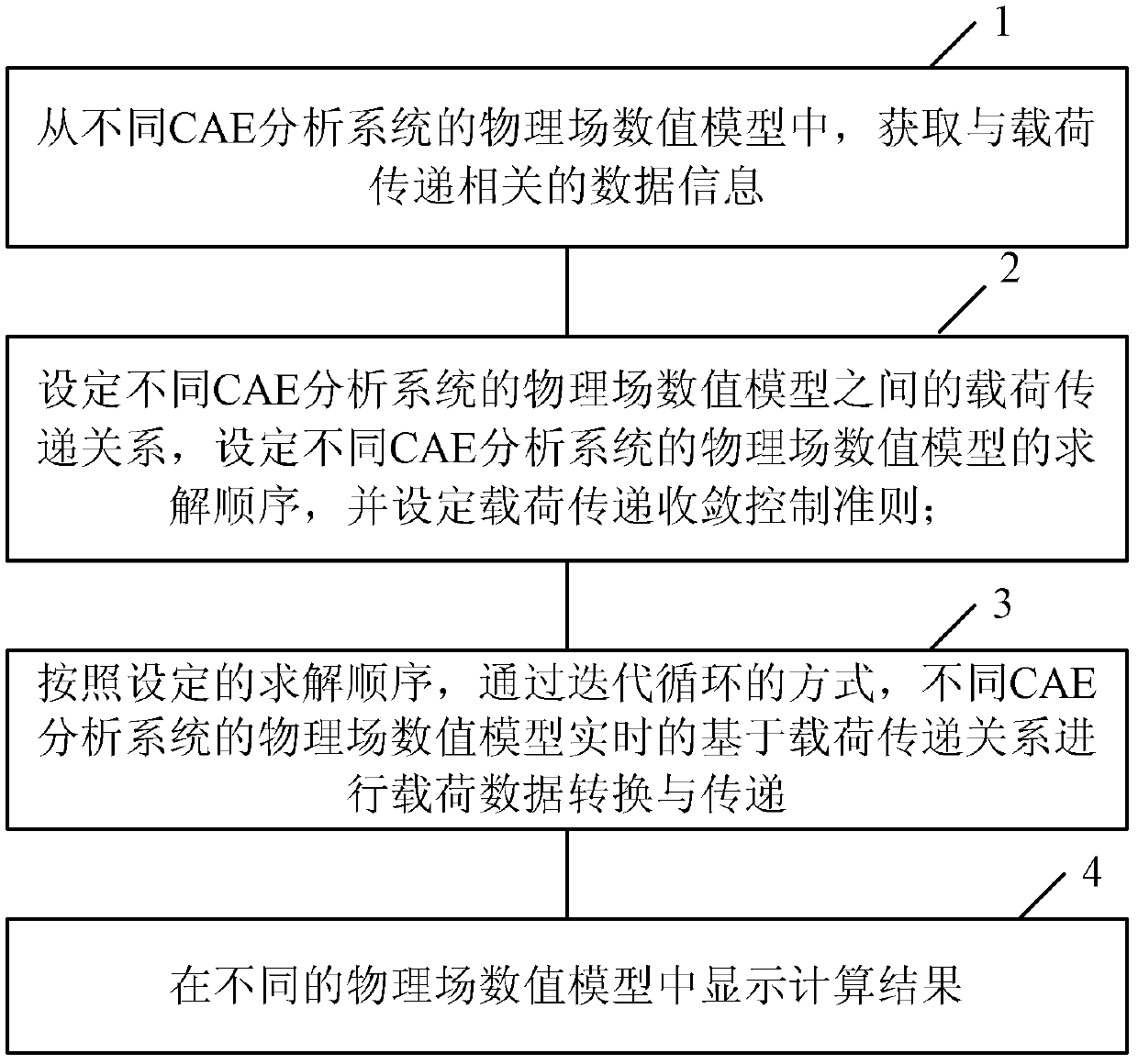
[0018] like figure 1 As shown, the engineering multiphysics coupling analysis method of the present invention includes the following steps:
[0019] Step 1: Obtain data information related to load transfer from the physical field numerical models of different CAE analysis systems.
[0020] Step 2: Set the load transfer relationship between the physical field numerical models of different CAE analysis systems, set the solution sequence of the physical field numerical models of different CAE analysis systems, and set the load transfer convergence control criteria.
[0021] Step 3: According to the set solution sequence, through an iterative loop, the physical field numerical models of different CAE analysis systems are converted and transferred in real time based on the load transfer relationship.
[0022] refer to figure 2 As shown, the step of performing load data conversion based on the load transfer relationship in real time for the physical field numerical models of different CAE analysis systems further includes the following steps:
[0023] 1: The load data conversion interface reads the load data of the physical field numerical model 1 in a CAE analysis system.
[0024] 2: The load data conversion interface performs mapping and interpolation operations on the load data, converts the load data of the physical field numerical model 1 to the grid of the physical field numerical model 2 in another CAE analysis system, and outputs the physical field numerical model 2. The payload data format required for the analysis.
[0025] 3: Another CAE analysis system reads in the load data on the grid converted to the physical field numerical model 2, and analyzes the model.
[0026] The present invention allows different meshing of different physical fields at the coupled interface when dealing with coupled interface loads or data transfer, such as image 3 shown ( image 3 In practice, the interface gap between different physical fields is zero) requires efficient mapping technology and interpolation technology, for this reason, the present invention adopts the Bucket Search method to improve the search efficiency, and adopts the linearity based on the local coordinates of the unit in the interpolation operation. interpolation method.
[0027] The linear interpolation method based on the local coordinates of the unit further includes the following steps: finding the unit and the local coordinate value of the target point on the source item grid, according to the value of each node of the source item grid unit, and the target point on the source item grid unit The local coordinate value of the target point is obtained by linear interpolation, such as Figure 4 shown; Figure 4 , the area A framed by the dotted line is the target grid, and the area B framed by the solid line is the source item grid.
[0028] Since the convergence of the interface transfer load is the key to ensure the load transfer accuracy of the coupling method, the present invention adopts the method of the moderation factor to control the transfer speed of the load data, and the steps are expressed as:
[0029] F i+1 =F i +α×(F ext -F i )
[0030] Among them, F i+1 is the load delivered to the loaded model at the i+1 iteration step, F i is the load delivered to the loaded model in the previous iteration step i, F ext is the current latest external load that should be applied, α is the relaxation factor, and the value is between (0, 1.0). The interface load convergence judgment condition is expressed as follows:
[0031] ||F i+1 -F i ||/||F i ||
[0032] where ε is an implementation-specific fraction and ||*|| is the vector modulo.
[0033] Step 4: Display the calculation results in different physics numerical models. With boundary conditions applied, analysis results are velocity, stress, displacement, temperature, or other quantities, displayed in the form of contours, streamlines, animations, and multiple plots that can be displayed in different physical models.
[0034] Before step 1, the following steps may also be included:
[0035] 1: Establish a mathematical model of the model in CAD format. The CAD format file refers to the three-dimensional model created by CAD software.
[0036] 2: Perform finite element or finite volume mesh division based on the CAD model to obtain a mesh model. This meshing can be done under general meshing tools or under CAE software with meshing capabilities.
[0037] 3: Import the mesh model into the corresponding CAE analysis system to establish the corresponding physical model. The physical model refers to the reflection of the real physical field in the computer through the program, including structural field, fluid field, temperature field, electrostatic field, magnetic field, electric field, piezoelectric field, etc.
[0038] 4: The CAE analysis system sets the analysis conditions of the physical field numerical model, sets the material parameters, applies the boundary conditions, sets the initial conditions of the calculation and the output adjustment control to complete the setting of the physical field numerical model under each CAE analysis system.
[0039] The following is an example of the specific process of the above analysis method by analyzing the thermal stress generated by the solid screw under the action of temperature load:
[0040] Step1: Open the GUI.
[0041] Step2: Import the geometry file in Step format.
[0042] Step3: Generate grid, including steps:
[0043] 1. Create geometric boundary conditions;
[0044] 2. Divide the mesh, and the mesh results are displayed as follows Figure 5shown;
[0045] 3. Save the file;
[0046] Step4: Create a physical model, which includes steps:
[0047] Step4.1: Set the thermal model;
[0048] Under the "Thermal" physical model
[0049] 1. Simulation settings;
[0050] 2. Import grid components;
[0051] 3. Specify the unit type;
[0052] 4. Loading material;
[0053] 5. Set material properties;
[0054] 6. Apply boundary conditions;
[0055] 7. Solve the thermal model;
[0056] 8. Display thermal results;
[0057] Step4.2: Set the solid physical model;
[0058] In the "Solid" environment
[0059] 1. Simulation settings;
[0060] 2. Import grid components;
[0061] 3. Specify the unit type;
[0062] 4. Loading material;
[0063] 5. Specify material properties;
[0064] 6. Set boundary conditions;
[0065] 7. Test and solve the solid model;
[0066] 8. Display the results.
[0067] Step5: Set the temperature-stress coupling problem, which includes the following steps:
[0068] 1. Delete irrelevant BCs;
[0069] 2. Set the coupling conditions;
[0070] 3. Create parallel solve groups.
[0071] Step6: Save the input and solve.
[0072] Step7: Display the result.
[0073] The invention provides a flexible, universal and convenient coupling tool platform across CAE software, which can perform process control, nonlinear iterative control, and load transfer control of multi-physics coupling analysis across different CAE analysis software, and complete complex complex Multiphysics coupled analysis. Compared with the traditional strong coupling method and the network-based data transfer tool and function control method, this method uses the functions of the existing CAE software to the maximum extent, and does not require any modification or new development for the CAE software with the existing IO interface. Multi-field coupling analysis can be performed directly under this technology platform. It not only saves research and development costs and software use costs, but also greatly improves the ease of use of coupled field analysis software. It is bound to play a positive role in the application and promotion of engineering multiphysics analysis in industrial design, and is conducive to the performance analysis of complex industrial problems. and innovative design.
[0074] The above description is only a preferred embodiment of the present invention, but the protection scope of the present invention is not limited to this. The equivalent replacement or change of the inventive concept thereof shall be included within the protection scope of the present invention.

PUM

no PUM

Description & Claims & Application Information

We can also present the details of the Description, Claims and Application information to help users get a comprehensive understanding of the technical details of the patent, such as background art, summary of invention, brief description of drawings, description of embodiments, and other original content. On the other hand, users can also determine the specific scope of protection of the technology through the list of claims; as well as understand the changes in the life cycle of the technology with the presentation of the patent timeline. Login to view more.

Similar technology patents

Classification and recommendation of technical efficacy words

Why Eureka
Try Eureka