Method for controlling field emission electronic divergence angle by using nano carbon tube

A technology of carbon nanotubes and a control method, which is applied to the parts, circuits, electrical components of discharge tubes/lamps, etc., can solve the problems of large divergence angle, complex structure and control, and high price, and achieves improved resolution, device Compact, dispersion-suppressing effect

Active Publication Date: 2012-07-18
SHANGHAI INST OF OPTICS & FINE MECHANICS CHINESE ACAD OF SCI
View PDF4 Cites 2 Cited by
  • Summary
  • Abstract
  • Description
  • Claims
  • Application Information

AI Technical Summary

Problems solved by technology

For electron lithography or electronic imaging technology that requires high resolution, such a large divergence angle cannot meet the requirements, and the electron beam needs to be collimated or focused
[0006] Although the traditional electron beam convergence methods, such as the magnetic lens or electrostatic lens technology used in the electron microscope, are relatively mature, their structure and control are relatively complicated, expensive, and more importantly, they cannot be used in close proximity between the electron source and the detection sample. used in field detection

Method used


Image

  • Method for controlling field emission electronic divergence angle by using nano carbon tube
  • Method for controlling field emission electronic divergence angle by using nano carbon tube
  • Method for controlling field emission electronic divergence angle by using nano carbon tube

Examples


Embodiment Construction

[0027] The present invention will be further described below in conjunction with the embodiments and accompanying drawings, but the protection scope of the present invention should not be limited thereby.

[0028] The present invention utilizes carbon nanotubes to the method for controlling the divergence angle of field emission electrons, comprising the following steps:

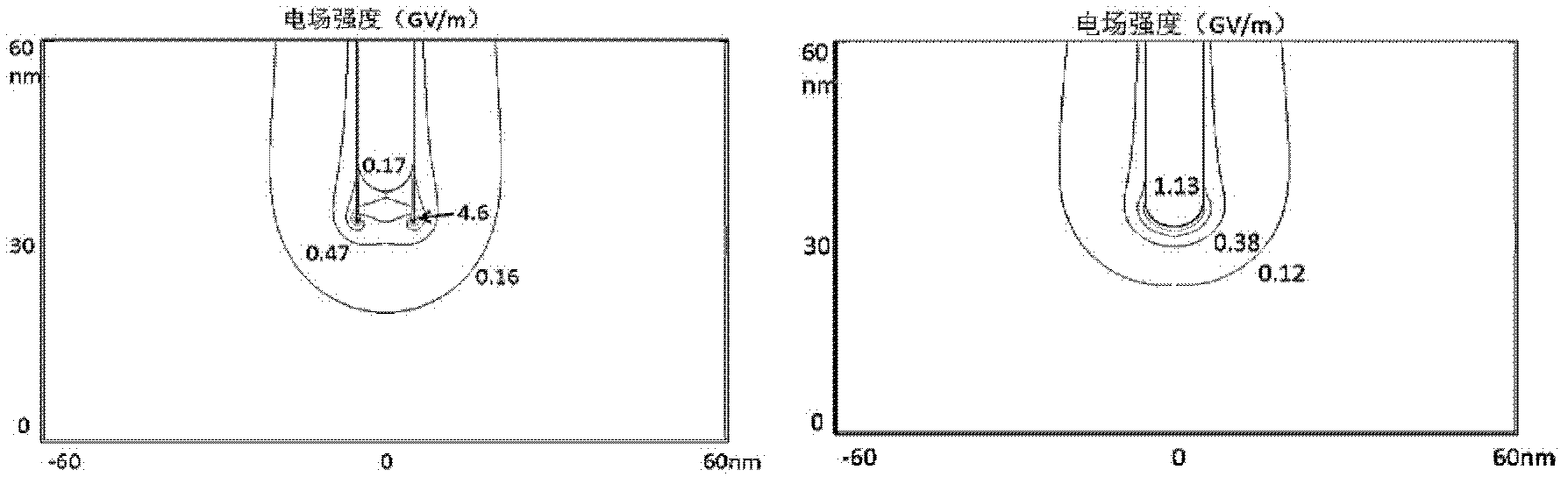
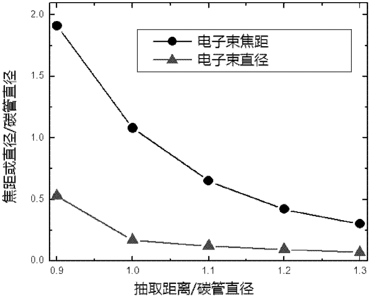
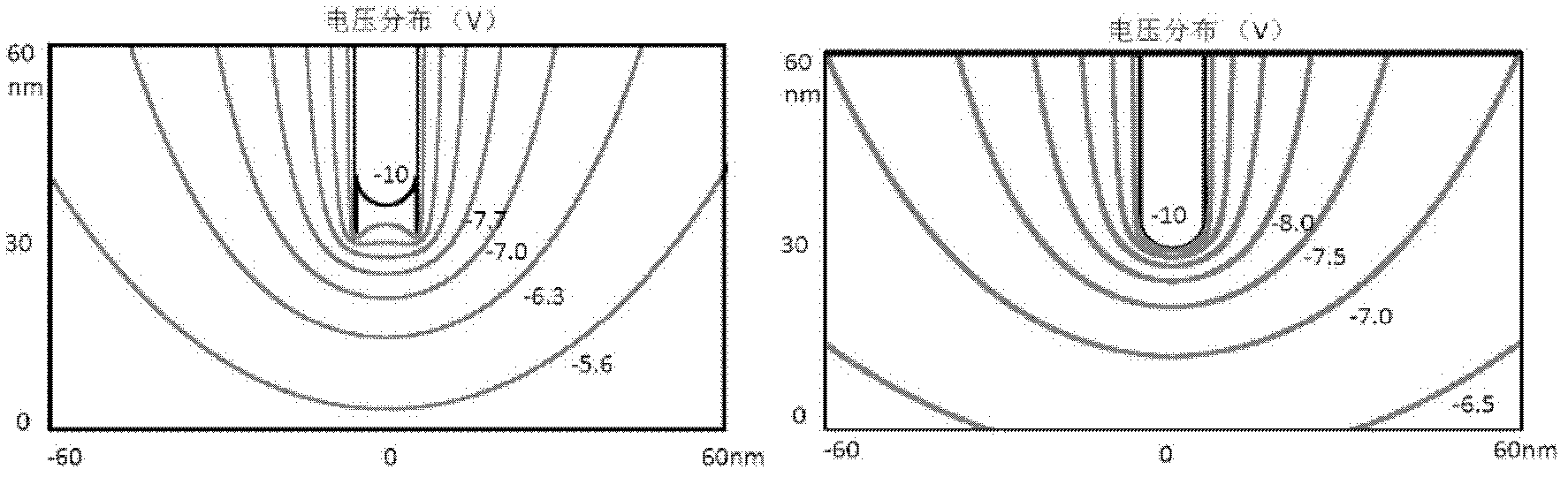
[0029] 1. Preparation of multiwall carbon nanotubes [Please refer to literature [2]. John Cumings and A. Zettl, Low-friction nanoscale linear bearing realized from multiwall carbon nanotubes, Science (2000) 289 , 602-604.]: Take out the multi-walled carbon nanotubes prepared by conventional methods (such as arc discharge method, laser ablation method, chemical vapor deposition method, etc.) On the metal support, the other end is pasted on a piezoelectric ceramic displacement controller with nanometer precision. Add a pulse voltage to the fixed end of the carbon tube, open the end of the outer wall of the c...


PUM


Abstract

The invention discloses a method for controlling a field emission electronic divergence angle by using a nano carbon tube. The method comprises the steps of: applying a voltage between the carbon tube and a positive pole to form electron field emission by using the multi-wall nano carbon tube as an electron source of field emission; and changing the electric-field distribution of a port of the nano carbon tube through regulating and selecting the length of the extracted outer wall of the nano carbon tube and the voltage applied to the nano carbon tube, controlling the field emission electronic divergence angle, collimation or convergence, and controlling the focusing distance of an electron beam. According to the invention, under the condition without any additional focusing device, the divergence, focusing or collimation of field-emitted electronics is controlled.

Description

technical field [0001] The invention relates to the field of electron field emission of carbon nanotubes, and relates to a method for controlling the divergence angle of field emission electrons by using carbon nanotubes. [0002] This patent can be used in electronic processing or imaging equipment that requires high-brightness electron sources and high-resolution. Such as electron lithography, electron microscope and electron diffraction device and so on. Especially in near-field detection, the focusing method without additional electron lens can eliminate the limitation of the distance between the electron source and the detection sample, thereby reducing the diffusion of the electron beam and greatly improving the resolution of the electronic imaging device. Background technique [0003] Since the discovery of carbon nanotubes in 1991, electron field emission devices based on carbon nanotubes have been widely studied all over the world due to their low bias voltage and ...

Claims


Application Information

Patent Timeline
Patent Type & Authority Applications(China)
IPC IPC(8): H01J1/304
Inventor 许灿华冷雨欣李闯宋立伟李儒新
Owner SHANGHAI INST OF OPTICS & FINE MECHANICS CHINESE ACAD OF SCI
Why Eureka
Try Eureka