
Repetition frequency compact pulse multiplier based on Fitch circuit

A technology of repetition frequency and multiplier, which is applied in the direction of conversion equipment without intermediate conversion to AC, and can solve problems such as insulation recovery time limiting repetition frequency, difficulty in realization, and large transformation ratio.

Inactive Publication Date: 2014-11-05
XI AN JIAOTONG UNIV
View PDF4 Cites 0 Cited by
  • Summary
  • Abstract
  • Description
  • Claims
  • Application Information

AI Technical Summary

Problems solved by technology

However, the pulse transformer needs to multiply the voltage of hundreds of volts to tens of kilovolts, so its transformation ratio is very large
This will bring about two problems: 1. The large transformation ratio requires that there should not be many primary windings, otherwise there will be too many secondary windings and it will be difficult to realize
In this way, in order to ensure that the pulse transformer does not saturate before the input pulse reaches its peak value, the cross-sectional area of ​​its magnetic core must be large, which leads to a large volume of the pulse transformer, which is not conducive to the miniaturization of the pulse source
2. Document [5] records that air insulation is sufficient for pulse transformers with an output voltage amplitude of 10kV or below, while pulse transformers with an output voltage amplitude between 10kV and 50kV require oil-paper hybrid insulation, which will greatly increase the weight of the pulse transformer. Not conducive to its miniaturization and portability
[0005] However, the circuit proposed in Document 6 has the following disadvantages: 1. The capacitor is charged through the resistor, the charging time is very long, and repeated operation cannot be achieved
2. The ball gap is used as the switch, and its insulation recovery time and electrode ablation also limit the repeated operation frequency of the whole system

Method used


Image

  • Repetition frequency compact pulse multiplier based on Fitch circuit
  • Repetition frequency compact pulse multiplier based on Fitch circuit
  • Repetition frequency compact pulse multiplier based on Fitch circuit

Examples


Embodiment 1

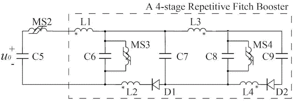
[0028] A four-stage pulse multiplier is designed, and its circuit diagram is shown in the attached image 3 :

[0029] 1. Four charging capacitors C6-C9 are placed side by side, and the upper end of C6 and C7, the lower end of C7 and C8, and the upper end of C8 and C9 are connected.

[0030] 2. The unconnected pins of adjacent capacitors (that is, the lower end of C6 and the upper end of C7, the lower end of C7 and the upper end of C8, the lower end of C8 and the upper end of C9) are connected together through coupling inductors. According to the terminal connection of the same name as shown in the figure, when the capacitor is charged, the sum of the current flowing through the coupled inductor is zero, which can be explained as follows. Assume that the charging waveform of each capacitor is consistent during charging, so its charging current i is the same at any moment. According to the coupled inductor connection in the figure, it can be obtained: 1 current i L1 = 4i.i ...

Embodiment 2

[0038] Such as Figure 4 As shown, the structure of the five-stage pulse multiplier is equivalent to the parallel connection of the final capacitor of the four-stage pulse multiplier, the series coupling of the inductor L18 and the capacitor C24, and the capacitor C24 is connected in parallel with the magnetic switch M13. In addition, in order to ensure that the net current flowing into the coupled inductor is zero during charging, L15 is connected in series with the coupled inductor L16 with the same number of turns, and the coupling direction of L14 and L17 is opposite to that of the four-stage pulse multiplier.

Embodiment 3

[0040] Such as Figure 5 As shown, it is an eight-stage pulse multiplier. Compared with a four-stage pulse multiplier, the structure of an eight-stage pulse multiplier is equivalent to two four-stage pulse multipliers cascaded. The coupling direction of L5 and L11 in the above figure is taken as opposite. The arrangement of the coupled inductors is to ensure that the net current flowing into the coupled inductors is zero when the eight-stage pulse multiplier is charging, and the coupling directions of the upper row of coupled inductors are consistent.

[0041] According to the above design method, pulse multipliers with different stages (N capacitors are N stages) can be designed, and they have the dual effects of pulse amplitude multiplication and rising edge compression.

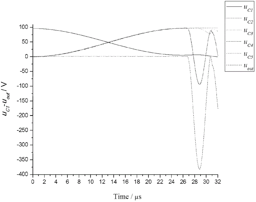
[0042] Using the Matlab Simulink module to simulate the circuit of the four-stage pulse multiplier, the capacitor voltages and output voltage waveforms of each stage are obtained, as shown in the attached...


PUM


Abstract

The invention discloses a repetition frequency compact pulse multiplier based on a Fitch circuit. The positive electrode of input voltage needing to be multiplied is connected to one end of the multiplier by a satiable inductor or a magnetic switch, and the negative electrode of the input voltage is directly connected with the other end of the multiplier; the multiplier comprises N capacitors connected in parallel, and a series circuit of a coupling inductor and a high-frequency silicon stack is connected between the two ends of the nth capacitor and the n+1th capacitor connected with the negative electrode of the input voltage; another coupling inductor is connected between the two ends of the n+1th capacitor and the n+2th capacitor connected with the positive electrode of the input voltage; n is equal to 1, 3, 5 ...; due to the arrangement of a plurality of dotted terminals of the coupling inductor, the condition that the sum of the flowing inductive current when the capacitors are charged counteracts to be zero can be ensured; a plurality of the dotted terminals of another coupling inductor are consistent in direction; and the two ends of the nth capacitor are connected with the satiable inductor in parallel. In the invention, the charging time is the pulse multiplier is short, and the voltage-second product of the satiable inductor is small; no electrode erosion and insulation recovery exist in the magnetic switch, so that the circuit can be operated under high repetition frequency.

Description

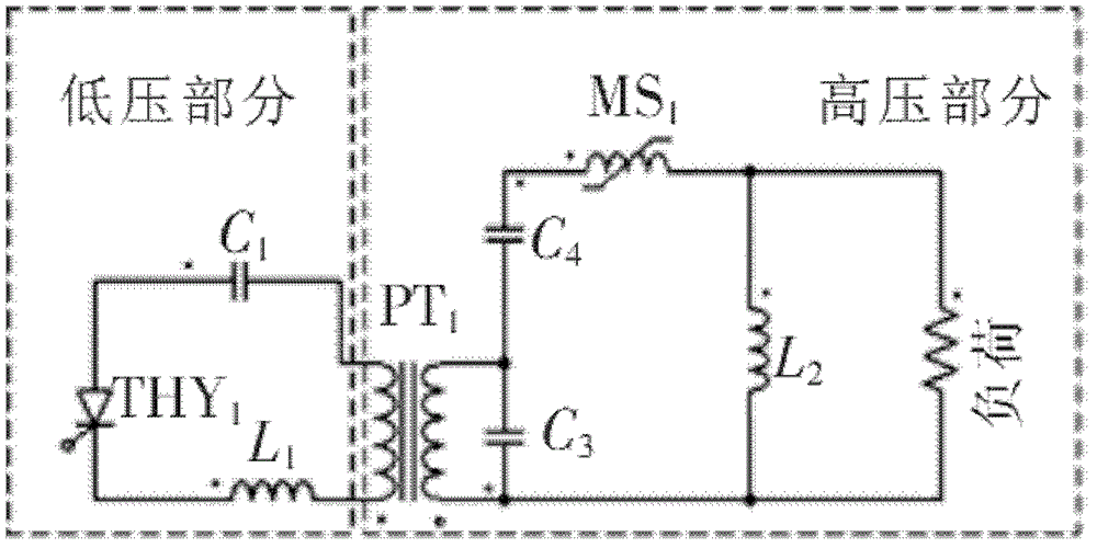
Technical field: [0001] The invention belongs to the field of pulse power, in particular to a repetition frequency pulse voltage doubler circuit. Background technique: [0002] The repetitive frequency pulse voltage doubler circuit widely used at this stage is a reset-free magnetic compression circuit, and its circuit structure is as attached figure 1 shown [1-2] . Low voltage charging capacitor C 1 and thyristor THY 1 (or IGBT [3] ), air core inductor L 1 (or magnetic switch [4] ) and pulse transformer PT 1 The primary windings are connected in series and form a closed loop. High voltage charging capacitor C 2 and C 3 With magnetic switch MS1 and air core inductor L 2 (or semiconductor disconnect switch [5] , the upper anode, the lower cathode) in series and form a closed loop. Pulse transformer secondary winding and high voltage charging capacitor C 3 connected in parallel to form a closed circuit. Load and air core inductance L 2 connected in parallel to f...

Claims


Application Information

Patent Timeline
Patent Type & Authority Patents(China)
IPC IPC(8): H02M3/06
Inventor 丁卫东任航吴佳玮
Owner XI AN JIAOTONG UNIV
Learn More