Environment-friendly papermaking process and environment-friendly papermaking equipment
A papermaking process and environmental protection technology, applied in the field of papermaking, can solve problems such as waste, power consumption, and complicated processes
- Summary
- Abstract
- Description
- Claims
- Application Information
AI Technical Summary
Problems solved by technology
Method used
Image
Examples
Embodiment 1
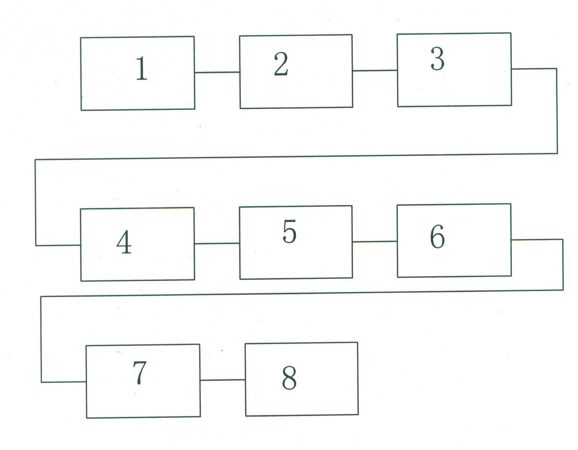
[0017] like figure 1 As shown, an environmentally friendly papermaking process: 1. Impurity separation: After the waste paper is cleaned, it is sent to the impurity separator through the conveyor belt, and the waste paper is separated into coarse pulp, scum and sediment. The sediment is cleaned regularly, and the scum is made of impurities. The scum collector above the separator is recovered and transported to the designated location; 2. Sand settling: the separated coarse pulp overflows from the screen hole above the impurity separator to the coarse stock tank for sand settling; 3. Sand removal: settling The rough pulp after sand is introduced into the sand remover by a pulp pump to remove sand; 4. Water separation: the coarse pulp after sand removal is connected to the inclined screen for water separation, and the separated water is collected in the sump below the inclined screen, and collected The water in the pool is recycled to the impurity separator, and the pulp on the ...
Embodiment 2
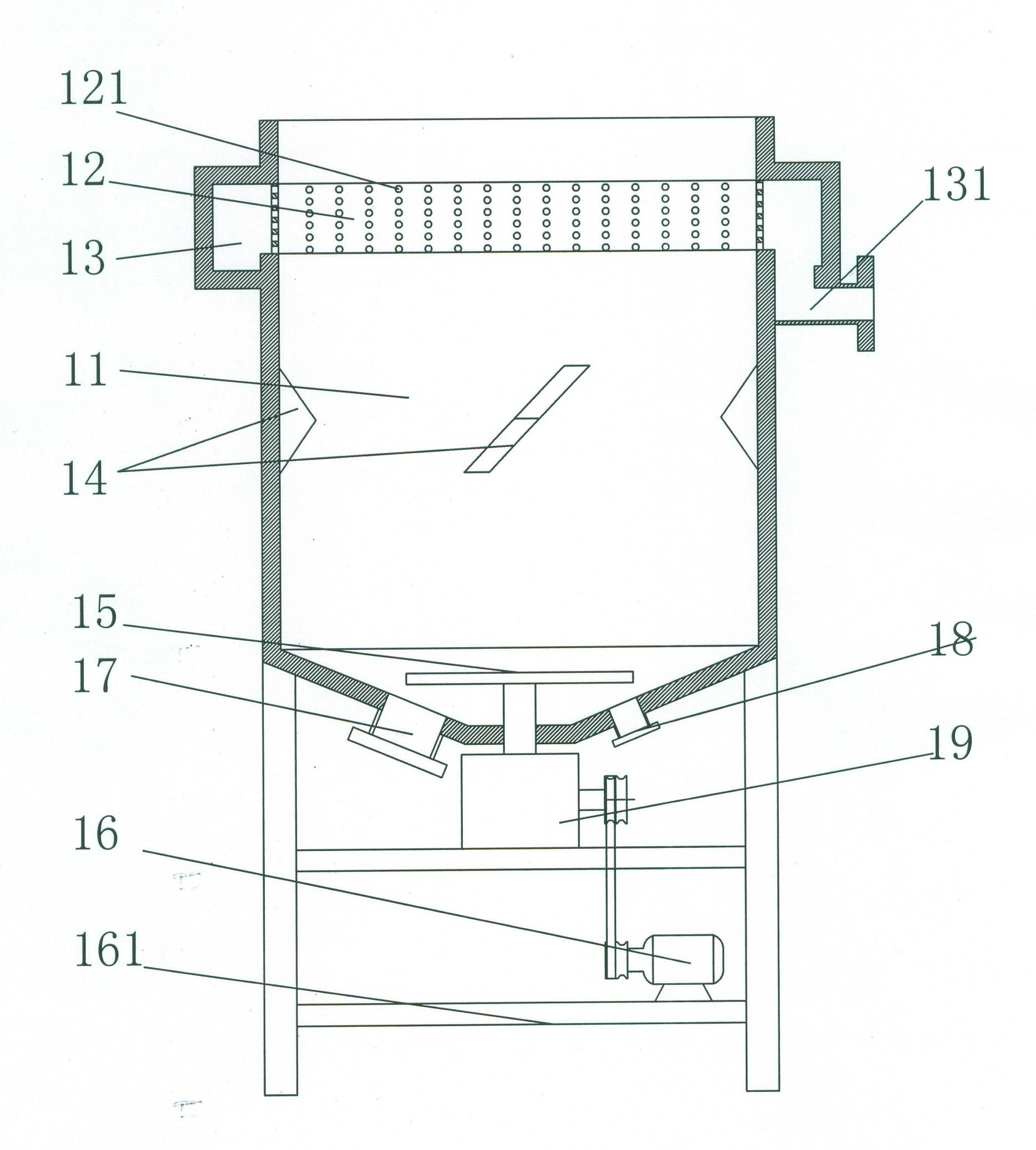
[0019] like figure 2 , Figure 4 As shown, the impurity separator can separate waste paper into coarse pulp, scum and sediment, including a cylinder 11, an annular sieve plate 12 arranged on the upper part of the cylinder 11, and a centrifugal impeller arranged at the bottom of the cylinder 11 15. The motor 16 that drives the centrifugal impeller 15, the outer side of the annular sieve plate 12 is provided with an annular collection tank 13, the bottom of the annular collection tank 13 is provided with a slurry outlet 131, the sieve holes 121 of the annular sieve plate 12 The aperture is 1 cm to 1.5 cm, which is conducive to the passage of coarse pulp. The centrifugal impeller 15 consists of a wheel disc 151, arc-shaped blades 152 uniformly distributed on the edge of the wheel disc 151, and welded on the wheel disc 151 and arc-shaped blades 152. The bump 153 increases the effect of centrifugation and crushing. The arc-shaped blade 152 is parallel to the cylinder wall. The in...
Embodiment 3
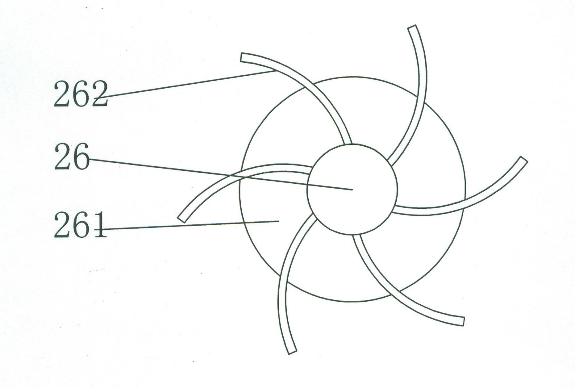
[0021] like image 3 , Figure 5 As shown, the high-concentration decomposition machine includes a cylinder 21, a conical sieve plate 24 located at the bottom of the cylinder 21, a centrifugal impeller 26 located at the bottom of the cylinder 21, a motor 27 driving the centrifugal impeller 26, and the cone The closed space on the lower side of the shaped sieve plate 24 is a fine pulp collection chamber 25, the bottom of the fine pulp collection chamber 25 is provided with a pulp outlet 28, and the sieve hole diameter of the conical sieve plate 24 is 0.15 cm to 0.35 cm. Facilitate the passage of fine pulp. The centrifugal impeller 26 consists of a wheel disc 261 and arc-shaped blades 262 evenly distributed on the edge of the wheel disc 261. The arc-shaped vanes 262 are parallel to the cylinder wall to increase the centrifugal and decomposition effects. The cylinder The inner wall of the body 21 is provided with a sloping plate 22 , the centrifugal impeller 26 is connected with...
PUM
| Property | Measurement | Unit |
|---|---|---|
| pore size | aaaaa | aaaaa |
| pore size | aaaaa | aaaaa |
Abstract
Description
Claims
Application Information
 - R&D
- Intellectual Property
- Life Sciences
- Materials
- Tech Scout
- Unparalleled Data Quality
- Higher Quality Content
- 60% Fewer Hallucinations
Browse by: Latest US Patents, China's latest patents, Technical Efficacy Thesaurus, Application Domain, Technology Topic, Popular Technical Reports.
© 2025 PatSnap. All rights reserved.Legal|Privacy policy|Modern Slavery Act Transparency Statement|Sitemap|About US| Contact US: help@patsnap.com


