Vehicle-mounted one-key constant-frequency power generation system and vehicle-mounted one-key constant-frequency power generation control system and method

A technology of constant frequency power generation and control system, applied in the direction of engine control, machine/engine, mechanical equipment, etc., can solve the problems of large inertia of alternator, high failure rate of electrical equipment, poor reliability, etc., to achieve simple operation and protection. The effect of electrical equipment

Active Publication Date: 2012-07-25
DONGFENG MOTOR CORP HUBEI
View PDF7 Cites 11 Cited by
  • Summary
  • Abstract
  • Description
  • Claims
  • Application Information

AI Technical Summary

Problems solved by technology

[0002] Some special-purpose vehicles are equipped with a large number of electrical equipment. In order to ensure constant frequency AC power output, the power supply system usually uses the power output of an independently installed turbine engine, which is connected with the shaft of the alternator through a coupling. When the engine starts or stops, due to the large inertia of the alternator, it brings excessive impact load, which leads to short life and poor reliability of the transmission system, which directly affects the high failure rate of electrical equipment and cannot be used normally.

Method used


Image

  • Vehicle-mounted one-key constant-frequency power generation system and vehicle-mounted one-key constant-frequency power generation control system and method
  • Vehicle-mounted one-key constant-frequency power generation system and vehicle-mounted one-key constant-frequency power generation control system and method
  • Vehicle-mounted one-key constant-frequency power generation system and vehicle-mounted one-key constant-frequency power generation control system and method

Examples


Embodiment Construction

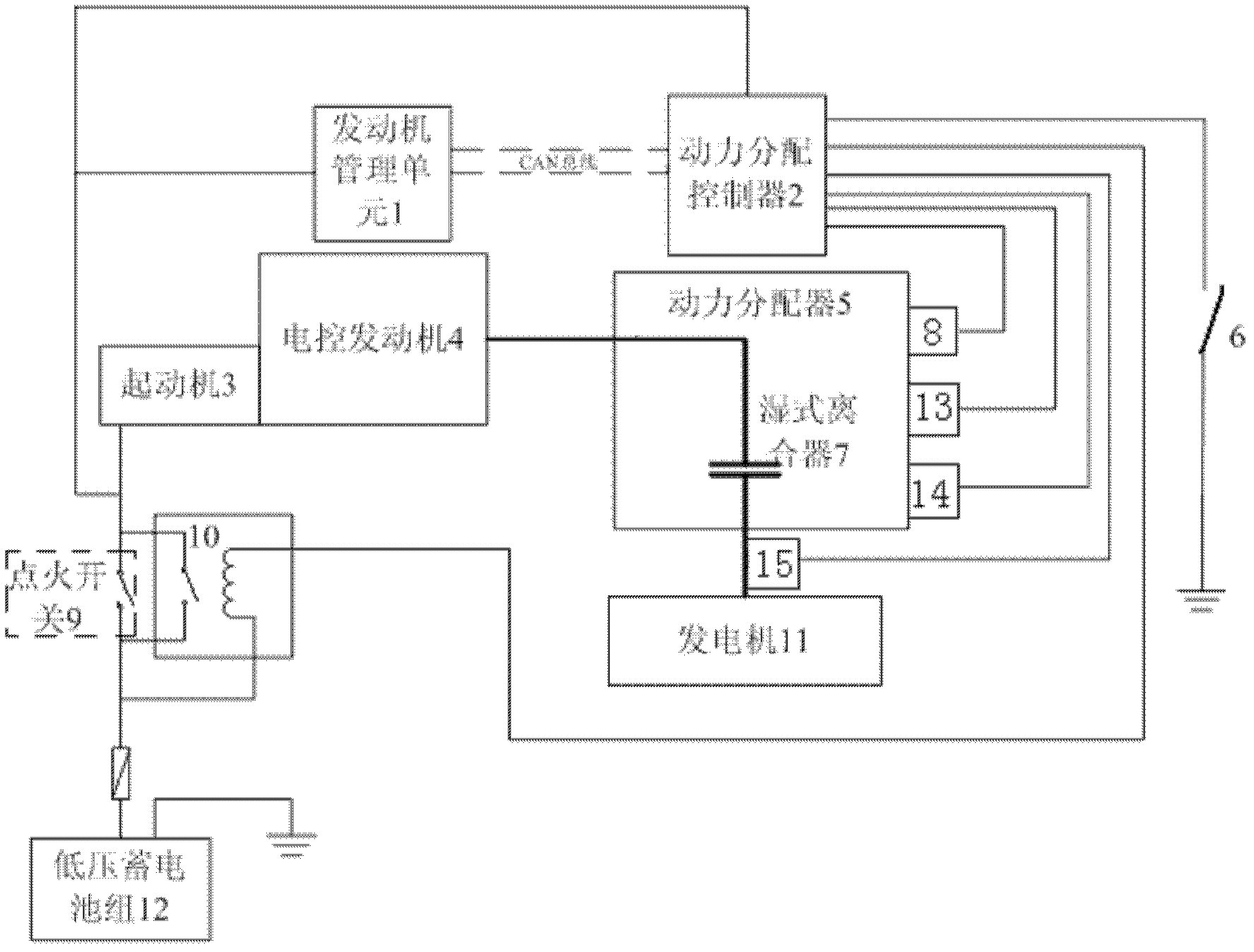
[0020] like figure 1 As shown, a vehicle-mounted one-button constant frequency power generation system of the present invention includes an engine management unit 1, an electronically controlled engine 4, a starter 3, a power splitter 5, a wet clutch 7, a clutch switch solenoid valve 8, and an alternator 11 1. One key power generation switch 6, the starter 3 is connected with the electric control engine 4 through a belt drive, the electric control engine 4 is connected with the power splitter 5 through the output shaft, and the gear set inside the power splitter 5 outputs the power to the wet clutch 7, and the other end of the wet clutch 7 is connected with the alternator 11.

[0021] The power splitter 5 includes an input shaft, an intermediate shaft and a plurality of output shafts, and the transmission between the input shaft and the intermediate shaft is through a bevel gear, so that the input shaft and the output shaft are distributed along the vertical direction. A pull...


PUM


Abstract

The invention provides a vehicle-mounted one-key constant-frequency power generation system and a vehicle-mounted one-key constant-frequency power generation control system and method. A starter is connected with an electrically controlled engine through a belt; the electrically controlled engine is connected with a power distributor through an output shaft; a gear group in the power distributor outputs power to one end of a wet type clutch; the other end of the wet type clutch is connected with an alternating current power generator; a power distribution controller is provided; an engine management unit is connected with the power distribution controller through a controller area network (CAN) bus; the input end of the power distribution controller is connected with a pressure sensor arranged on the wet type clutch, an engine oil temperature sensor arranged on the power distributor, a rotating speed sensor arranged on the output shaft of the wet type clutch and a one-key power generation switch; and the output end of the power distribution controller is connected with a clutch switching electromagnetic valve. Due to one-key operation, stable constant-frequency power can be supplied to a vehicle-mounted electric appliance within two seconds, so that the electric appliance is started quickly; and the vehicle-mounted one-key constant-frequency power generation system is especially suitable for special vehicles with quick power supply response requirements.

Description

technical field [0001] The invention belongs to a vehicle-mounted power supply system, and specifically relates to a vehicle-mounted one-button constant-frequency power generation system, a control system and a control method that utilizes the power output of a high-power electronically controlled engine to realize a vehicle-mounted generator based on automatic control technology, and is suitable for being equipped with a vehicle-mounted power supply system. Various special vehicles for electrical equipment. Background technique [0002] Some special-purpose vehicles are equipped with a large number of electrical equipment. In order to ensure constant frequency AC power output, the power supply system usually uses the power output of an independently installed turbine engine, which is connected with the shaft of the alternator through a coupling. When the engine starts or stops, due to the large inertia of the alternator, it brings excessive impact load, which leads to short...

Claims


Application Information

Patent Timeline
Patent Type & Authority Applications(China)
IPC IPC(8): F02D29/06
Inventor 马良杰寇西征张志勇夏佳磊许杰
Owner DONGFENG MOTOR CORP HUBEI
Why Eureka
Try Eureka