Absorption stage, placing stage and exposure apparatus

An adsorption table and adsorption hole technology, applied in the directions of screws, nuts, bolts, etc., can solve the problems of scratches on the surface of the workpiece, reduced product accuracy, and dust contamination of the workpiece, so as to prevent the reduction of product accuracy and the change of workpiece posture. Effect

Inactive Publication Date: 2012-07-25
KK TOPCON
View PDF8 Cites 12 Cited by
  • Summary
  • Abstract
  • Description
  • Claims
  • Application Information

AI Technical Summary

Problems solved by technology

[0007] However, if constituted like this, it is necessary to protrude and insert the claws on the workpiece placed on the carrying surface, which increases the time (processing capacity) required for mask pattern formation; Pushing the workpiece by the jaws may scratch the surface of the workpiece, and the action of the jaws may also cause the workpiece to be contaminated with dust.
Furthermore, there is a possibility that the accuracy of the product may be lowered due to the above

Method used


Image

  • Absorption stage, placing stage and exposure apparatus
  • Absorption stage, placing stage and exposure apparatus
  • Absorption stage, placing stage and exposure apparatus

Examples


Embodiment Construction

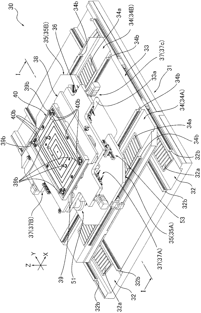
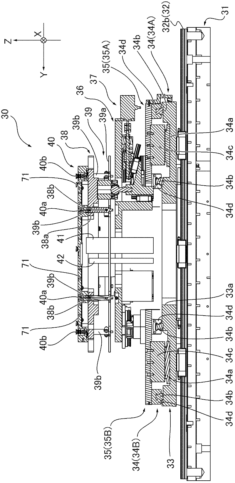
[0066] Next, an embodiment of the mounting table 30 according to the present invention will be described with reference to the drawings.

[0067] (Example)

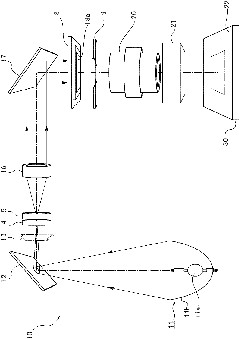
[0068] First, the schematic structure of the exposure apparatus 10 using the stage 30 which concerns on this invention is demonstrated. figure 1 It is an explanatory drawing which schematically shows the structure of the exposure apparatus 10 which is an example of the exposure apparatus concerning this invention. Exposure device 10 such as figure 1 As shown, there are in order from the exit side along the optical axis direction: a light source 11, a cold mirror 12, an exposure shutter 13, an ultraviolet bandpass filter 14, an integrating lens 15, a collimating lens 16, a plane mirror 17, a mask table 18, Mask blind section 19, projection lens 20, magnification correction section 21, and stage 30 (projection exposure stage). The exposure light of this exposure apparatus 10 uses ultraviolet rays.

[0069] The light sou...


PUM


Abstract

The invention provides an absorption stage, wherein workpieces can be held in a flat state without increasing the working time and lowering the product accuracy. When the absorption stage (40) is in use, a workpiece (22) are held on a flat loading surface (40b). The workpiece (22) is exposed to light so as to be imaged as a predetermined mask pattern, wherein the absorption stage comprises a fixed adsorption mechanism (60) capable of absorbing the workpiece (22) to fix the workpiece (22) relative to the flat loading surface (40b); a plane adsorption mechanism (70) capable of enabling the workpiece (22) to abut against the loading surface (40b) and provided with a plurality of planar adsorption holes (71) opened on the loading surface (40b).

Description

technical field [0001] The present invention relates to a suction table for holding substrates (hereinafter referred to as workpieces) such as printed circuit boards and liquid crystal substrates by suction, and an exposure apparatus equipped with the suction table. Background technique [0002] Photolithography is widely used in various fields. Using an exposure device, a predetermined mask pattern is exposed on the surface of a workpiece coated with a photosensitive material such as photoresist, and then a mask pattern is formed on the substrate through an etching process. Die patterns, printed circuit boards and liquid crystal substrates are also manufactured using exposure equipment. In such an exposure apparatus, a projection lens is used to form an image of exposure light transmitted through a mask on which a predetermined pattern is formed on the surface of a workpiece, thereby forming a predetermined mask pattern on the workpiece. Among such exposure apparatuses, a ...

Claims


Application Information

Patent Timeline
Patent Type & Authority Applications(China)
IPC IPC(8): G03F7/20H01L21/683
CPCF16B39/12H01R4/38H02G7/20
Inventor 吉田茂落合亮
Owner KK TOPCON
Why Eureka
Try Eureka