Non-inductive coil for high-temperature superconducting resistance-type current restrictor

A technology of high-temperature superconducting and non-inductive coils, which is applied in superconducting magnets/coils, usage of superconducting elements, coil manufacturing, etc. To avoid problems such as large belt length, to achieve the effects of ensuring safety and stability, simplifying the structure, and reducing processing difficulty

Inactive Publication Date: 2012-07-25
INST OF ELECTRICAL ENG CHINESE ACAD OF SCI +1
View PDF5 Cites 13 Cited by
  • Summary
  • Abstract
  • Description
  • Claims
  • Application Information

AI Technical Summary

Problems solved by technology

[0003] The purpose of the present invention is to overcome the defects of the prior art, such as complex structure, large inner diameter, difficult machining, easy damage to high-temperature superconducting strips, and large length of a single superconducting strip, and propose a double-band winding The non-inductive pie coil structure

Method used


Image

  • Non-inductive coil for high-temperature superconducting resistance-type current restrictor
  • Non-inductive coil for high-temperature superconducting resistance-type current restrictor
  • Non-inductive coil for high-temperature superconducting resistance-type current restrictor

Examples


Embodiment Construction

[0017] The present invention will be further described below in conjunction with the accompanying drawings and specific embodiments.

[0018] The present invention adopts the typical product dimensions of the commercially produced second-generation high-temperature superconducting tapes 12 and 13: the thickness is 0.1-0.3 mm, and the width is 4-12 mm. Under the condition of liquid nitrogen temperature and no external magnetic field, the critical current I of the high temperature superconducting strip 12, 13 unit width C Can reach 210A / cm.

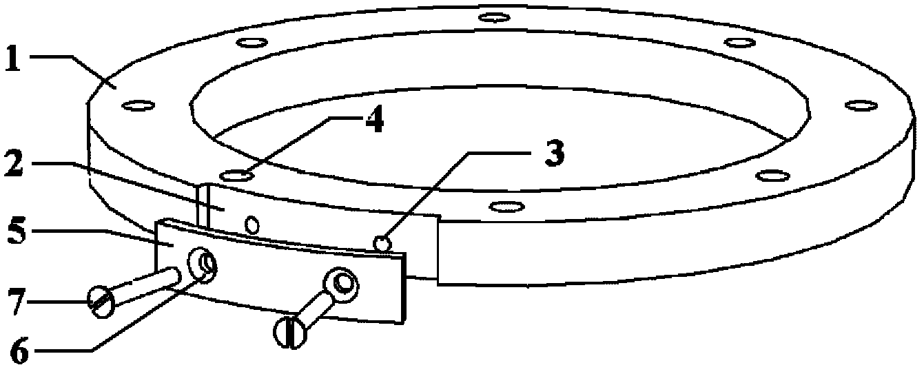
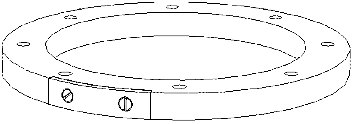
[0019] The present invention mainly includes a non-inductive cake-type coil skeleton 22 composed of a glass fiber reinforced plastic ring 1 and a copper connection piece 5, an inner high-temperature superconducting tape 12, an outer high-temperature superconducting tape 13, a spacer layer 14, lead terminals, coil splints and multiple sets of sinks. Parts such as head bolt 7,20,21.

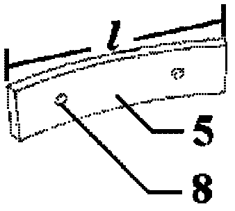
[0020] The width of the copper connecting piece 5 and th...


PUM

PropertyMeasurementUnit
lengthaaaaaaaaaa

Abstract

A non-inductive coil for a high-temperature superconducting resistance-type current restrictor includes a non-inductive cake-type bobbin consisting of a glass reinforced plastic ring (1) and a red copper connection sheet (5). The glass reinforced plastic ring (1) has an arch-shaped slot (2) with a length equal to the effective length l of the outer arc surface of the red copper connection sheet (5); the red copper connection sheet (5) is embedded in the slot (2); and the outer arc surface of the red copper connection sheet (5) is on the same annular surface of the outer arc surface of the glass reinforced plastic ring (1). Two coil clamp plates (19) are concentrically fixed on both sides of the non-inductive cake-type bobbin through countersunk screws. One ends of two equal-length parallel-wound superconducting tapes are superposed and aligned, and are welded on the red copper connection sheet (5) of the non-inductive cake-type bobbin at the same time. The two superconducting tapes are wound in parallel in the same direction, and a spacer layer is laid on the inner side of each superconducting tape in the same direction. Two lead terminals are fixed on one side of the coil on the outer edge of the lower coil clamp plate (19), and two superconducting tapes are respectively soldered on the corresponding lead terminals. The upper coil clamp plate is concentrically fixed on the upper side of the non-inductive cake-type coil through countersunk screws.

Description

technical field [0001] The invention relates to a coil for a resistance type fault current limiter, in particular to a non-inductive double-wrapped cake coil for a high temperature superconducting resistance type fault current limiter. Background technique [0002] At present, in order to adapt to the rapid development of the national economy, the continuous increase of the scale of the power grid and the continuous improvement of the degree of interconnection, my country's power grid is developing in the direction of ultra-large scale. However, the stability problem of my country's power grid has become increasingly serious, and the security and reliability of the power grid are under enormous pressure. Short-circuit faults are one of the serious faults that endanger the safety of power systems and cause huge economic losses. The resistance-type high-temperature superconducting current limiter based on the second-generation high-temperature superconducting tape uses the que...

Claims


Application Information

Patent Timeline
Patent Type & Authority Applications(China)
IPC IPC(8): H01F6/06H01F41/04H02H9/02
CPCY02E40/69Y02E40/60
Inventor 张京业戴少涛赵连岐张东徐小飞吴明建施飞滕玉平许熙周微微王子凯林良真肖立业
Owner INST OF ELECTRICAL ENG CHINESE ACAD OF SCI
Why Eureka
Try Eureka