Dynamic tunable microstrip antenna used in complex radio-wave environment and tuning method thereof

A technology of microstrip antenna and microstrip feeder, which is applied to the structural connection of antenna and antenna grounding switch, and the device that enables the antenna to work in different bands at the same time. It can solve the problems of difficult hardware reconfiguration and achieve stable performance and convenient operation. , to achieve real-time and reliable results

Inactive Publication Date: 2013-12-04
SHENZHEN TINNO WIRELESS TECH
View PDF2 Cites 0 Cited by
  • Summary
  • Abstract
  • Description
  • Claims
  • Application Information

AI Technical Summary

Problems solved by technology

[0007] In view of this, the object of the present invention is to provide a dynamically tunable microstrip antenna and its tuning method for complex radio wave environments. In view of the current situation that the best receiving frequency is fixed, if it is used in different frequency bands or different resonance points, its hardware reconstruction is difficult to realize, and a method for tuning the resonance point of the microstrip antenna state is proposed.

Method used


Image

  • Dynamic tunable microstrip antenna used in complex radio-wave environment and tuning method thereof
  • Dynamic tunable microstrip antenna used in complex radio-wave environment and tuning method thereof
  • Dynamic tunable microstrip antenna used in complex radio-wave environment and tuning method thereof

Examples


Embodiment Construction

[0030] In order to make the object, technical solution and advantages of the present invention clearer, the present invention will be further described in detail below in conjunction with the accompanying drawings and embodiments.

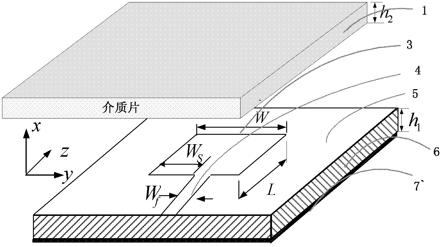
[0031] see figure 1 , introduces the structure composition of the dynamically tunable microstrip antenna used in the complex radio wave environment of the present invention. The basic structure of the microstrip antenna is almost the same as that of other microstrip antennas, and it is also composed of a rectangular microstrip antenna circuit 3, a strip-shaped microstrip feeder circuit 4, a filling medium 6 between a dielectric substrate 5 and a metal ground plate 7. composition. Wherein the rectangular microstrip antenna circuit 3 is located at the center of the surface of the dielectric substrate 5, and the middle of one end side of the microstrip antenna circuit 3 is connected to a microstrip feeder circuit 4 which takes the central axis of the...


PUM


Abstract

The invention relates to a dynamic tunable microstrip antenna used in a complex radio-wave environment and a tuning method thereof. A dielectric sheet tuning part is covered on the whole surface of a dielectric substrate of the microstrip antenna, and an emission signal working frequency band or a resonance point of the microstrip antenna can be selected and fine-tuned by only performing online detection and adjustment on the thickness of the dielectric sheet tuning part; or voltage is loaded at the two ends of one dimension, two dimensions or three dimensions selected arbitrarily from the three-dimensional direction of the dielectric sheet tuning part, and dielectric constants in the corresponding directions can be adjusted in real time by changing the loading voltage so as to enable the dielectric constants to be positioned in a resonance frequency band of the microstrip antenna. A layer of plasma cloud tuning part for simulating an outer-layer spatial environment is further arranged on the dielectric sheet tuning part, and the emission signal working frequency band or the resonance point of the microstrip antenna can be selected and fine-tuned by only performing online detection and selection on the thickness of the plasma cloud tuning part. The dynamic tunable microstrip antenna disclosed by the invention can dynamically tune the working frequency of the microstrip antenna in the complex radio-wave environment and has the advantages of simple structure, convenience in operation, stability in working, low cost, easiness in construction and small volume.

Description

technical field [0001] The invention relates to a dynamically tunable microstrip antenna used in complex radio wave environments and a tuning method thereof, belonging to the technical field of resonant microstrip antennas. Background technique [0002] With the development of wireless communication technology and the diversification of business requirements, especially in the complex radio wave environment of aerospace, remote sensing and telemetry, or the high-speed operation of ground high-speed rail, it will bring certain difficulties to real-time communication. Therefore, how to make real-time communication acceptable Wireless communication signals in different resonant frequency bands have become a necessary technical means for modern communication. [0003] However, when the flying body is flying at high speed (flying speed reaches Mach 10 and above), due to the intense friction between the surface of the flying body (or carrier) and the air, a large amount of plasma ...

Claims


Application Information

Patent Timeline
Patent Type & Authority Patents(China)
IPC IPC(8): H01Q13/08H01Q1/38H01Q1/50H01Q5/01H01Q5/10
Inventor 刘芳史信荣刘元安吴永乐黎淑兰于翠萍苏明
Owner SHENZHEN TINNO WIRELESS TECH
Why Eureka
Try Eureka