
Low-noise amplifier in multi-mode navigation type radiofrequency chip

A low-noise amplifier and radio frequency chip technology, applied in high-frequency amplifiers, improved amplifiers to expand bandwidth, improved amplifiers to reduce noise effects, etc., can solve problems such as multi-power, weak signal strength, and large local vibration amplitude, and achieve design Reasonable, improved anti-interference performance, low DC power consumption effect

Inactive Publication Date: 2012-07-25
常州安倍利电子科技有限公司 +1
View PDF3 Cites 0 Cited by
  • Summary
  • Abstract
  • Description
  • Claims
  • Application Information

AI Technical Summary

Problems solved by technology

Since the satellite navigation signal is susceptible to interference, resulting in the reduction of navigation accuracy, the accurate positioning function cannot be realized. Therefore, an amplifier needs to be installed at the front end of the satellite navigation receiver to amplify the weak radio frequency satellite signal
[0003] Existing amplifiers usually use a low-gain low-noise amplifier (LNA) to improve system linearity and power consumption. However, the low-gain LNA requires a mixer with a lower noise figure in order to maintain the overall system noise performance. Such a mixer would likely dissipate more power and require a large LO amplitude, i.e., cascading a low-gain LNA with a low-noise Compared with the mixer cascade, it does not reflect the practical advantage in the total power consumption
For the satellite navigation signal itself, the nonlinearity of the front end is not a very important problem. The received signal strength is actually very weak and contains mainly thermal noise. The linearity requirements of the system are mainly limited by external interference. signal, so the requirements for linearity will be slightly relaxed, but the requirements for low noise characteristics of the receiving system will be improved
Therefore, low-gain low-noise amplifiers (LNAs) are not suitable for amplifying weak RF satellite signals

Method used


Image

  • Low-noise amplifier in multi-mode navigation type radiofrequency chip
  • Low-noise amplifier in multi-mode navigation type radiofrequency chip

Examples


Embodiment Construction

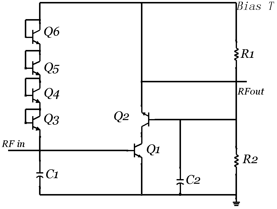
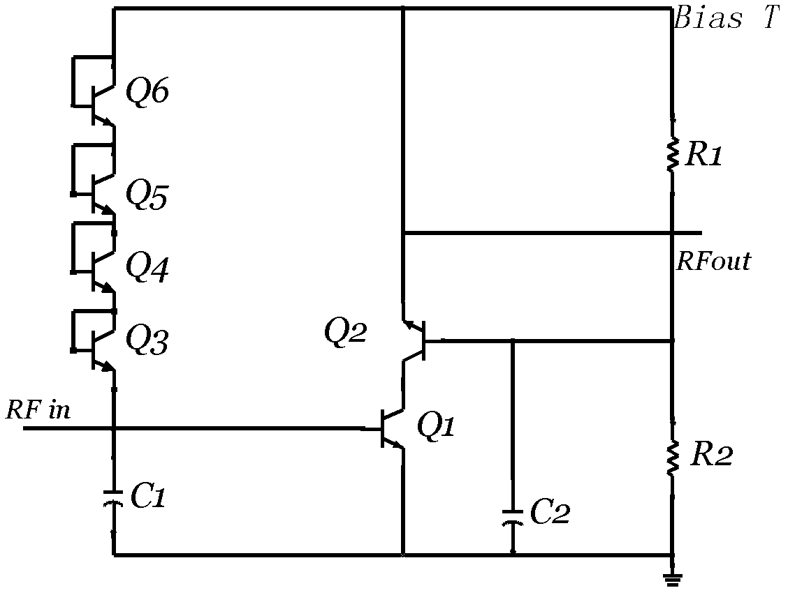
[0011] Embodiments of the present invention are described in further detail below in conjunction with the accompanying drawings:

[0012] A low-noise amplifier in a multi-mode navigation radio frequency chip is the key component of the satellite navigation receiver. Its main function is to amplify the weak signal received by the antenna from the air, reduce noise interference, and improve the sensitivity of the received signal for The system demodulates the required information data, and its noise, linearity and matching performance directly affect the performance of the entire receiving system.

[0013] The low noise amplifier of the present invention, such as figure 1 As shown, it includes two amplifier tubes Q1, Q2 and a diode chain. The diode chain is composed of four transistors Q3, Q4, Q5, and Q6 whose bases and collectors are short-circuited. The amplifier tubes Q1 and Q2 adopt a cascode connection structure, the base of the amplifier tube Q1 is connected to the radio ...


PUM


Abstract

The invention relates to a low-noise amplifier in a multi-mode navigation type radiofrequency chip, which is technically characterized by comprising two amplifying tubes Q1 and Q2 and a diode chain. The amplifying tubes Q1 and Q2 are in cascode connection structure, a base electrode of the amplifying tube Q1 is connected with the radiofrequency input signal RFin, the radiofrequency output signal RFout is outputted from an emitter electrode of the amplifying tube Q2, and the diode chain is connected between the base electrode of the amplifying tube Q1 and the emitter electrode of the amplifying tube Q2. The low-noise amplifier having the cascode connection structure is reasonable in design, and the diode chain is connected in a feedback network between the output end and the input end, and thus the satisfactory wideband characteristic can be achieved, enough gain can be obtained with lower direct-current power consumption, and interference resistance is improved.

Description

technical field [0001] The invention belongs to the field of radio frequency integrated circuits, in particular to a low-noise amplifier in a multi-mode navigation radio frequency chip. Background technique [0002] At present, satellite navigation receivers are used more and more widely. The satellite navigation receiver relies on the received weak radio frequency satellite signal to work. The frequency of the satellite navigation signal is B1 (1561.098±2.046)MHz, the frequency point of L1: (1575.42±1.023)MHz, and the input receiving level: -110dBm~- 65dBm. Since the satellite navigation signal is susceptible to interference, resulting in the reduction of navigation accuracy, the accurate positioning function cannot be realized. Therefore, an amplifier needs to be installed at the front end of the satellite navigation receiver to amplify the weak radio frequency satellite signal. [0003] Existing amplifiers usually use a low-gain low-noise amplifier (LNA) to improve syst...

Claims


Application Information

Patent Timeline
Patent Type & Authority Applications(China)
IPC IPC(8): H03F1/42H03F1/26H03F3/189
Inventor 申研王博
Owner 常州安倍利电子科技有限公司
Learn More