Two-phase opposed super magnetostrictive self-sensing driver

A technology of giant magnetostrictive and giant magnetostrictive rods, which is applied to piezoelectric effect/electrostrictive or magnetostrictive motors, valve devices, engine components, etc. To solve problems such as heavy weight, achieve the effect of improving system response speed and control accuracy, enhancing system reliability, and reducing costs

Inactive Publication Date: 2013-07-31
BEIJING UNIV OF TECH
View PDF6 Cites 2 Cited by
  • Summary
  • Abstract
  • Description
  • Claims
  • Application Information

AI Technical Summary

Problems solved by technology

[0002] In the field of hydraulic servo control, the traditional electromagnetic torque motor has complex structure, large volume and weight, narrow working frequency, low energy density, low resolution, and poor anti-interference ability. It is difficult to meet the requirements of modern industry for hydraulic servo control systems. limit
With the development of hydraulic servo valves in the direction of high pressure, large flow, high frequency response, high and low temperature environment adaptability, and anti-interference, traditional electro-hydraulic servo valves are difficult to meet the requirements, and with advanced manufacturing technology, modern design technology and microelectronics The development of technology and the application of new functional materials, the research and development of hydraulic servo valves with new drive technology, new drive structure and high frequency response have become an important direction for the development of servo control technology

Method used


Image

  • Two-phase opposed super magnetostrictive self-sensing driver
  • Two-phase opposed super magnetostrictive self-sensing driver
  • Two-phase opposed super magnetostrictive self-sensing driver

Examples


Embodiment Construction

[0022] The present invention will be further described below in conjunction with the accompanying drawings and specific embodiments.

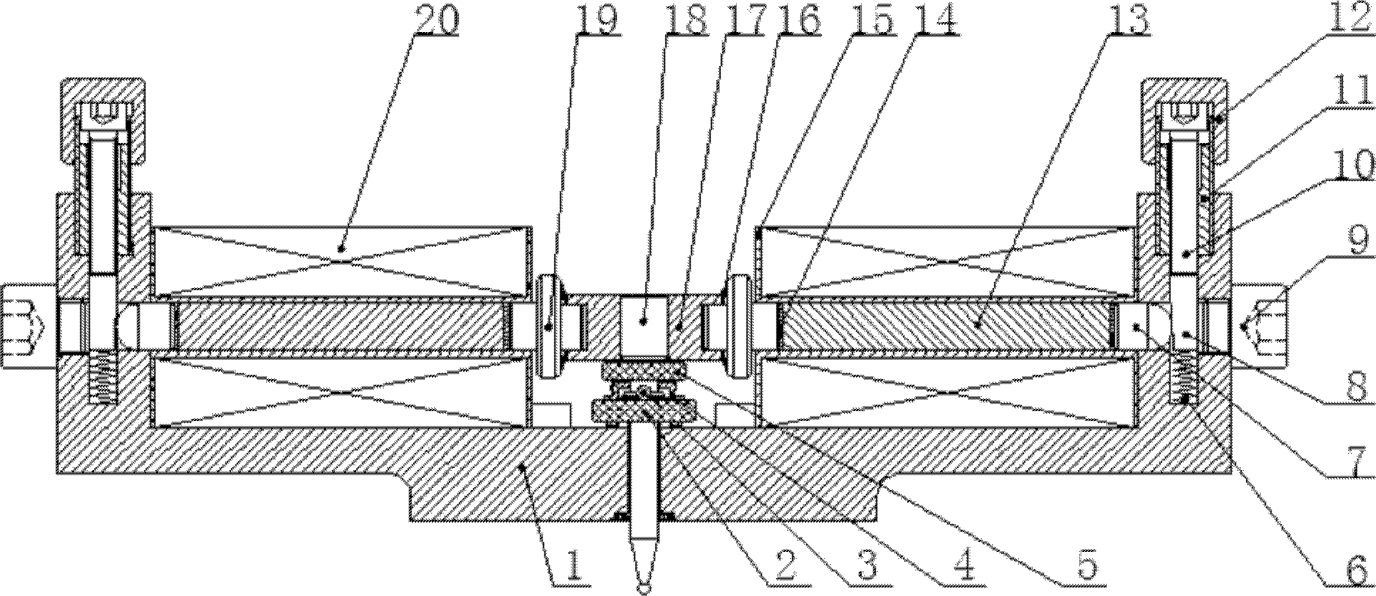
[0023] Such as Figures 1 to 9The novel structure of the dual-phase opposing giant magnetostrictive self-sensing driver shown in the present invention is mainly composed of a giant magnetostrictive self-sensing driver and a dual-output digital control power supply with self-sensing signal detection and feedback functions. The coupling between two self-sensing drive components with symmetrical structure is used to convert the input current signal into the displacement of the drive rod and the output of the driving force, and the dual-output numerical control power supply with self-sensing signal detection and feedback function is The two drive coils provide a stable differential voltage and a suitable drive current, and feed back the deflected displacement information of the connector 17 to the digital control part of the numerical control power...


PUM


Abstract

The invention discloses a two-phase opposed super magnetostrictive self-sensing driver, relates to a super magnetostrictive material self-sensing technology and a micro drive technology and belongs to the technical fields of micro drive and electrical control. According to the two-phase opposed super magnetostrictive self-sensing driver disclosed by the invention, the driving and self-sensing function of the driver is achieved by using magnetostriction and converse magnetostriction effects of a super magnetostrictive rod; two self-sensing driving assemblies are symmetrically arranged on two sides of a connecting piece (17) by disc springs (16) for mutually coupling to output a certain displacement and driving force; the pre-compression of the super magnetostrictive rod is accurately controlled and finely adjusted, so that the super magnetostrictive rod works in a linear interval; stable differential voltage is applied to two driving coils by a dual-output digital control power supply with a self-sensing detection and feedback function and a self-sensing signal is monitored in real time by using a real-time dynamic balance signal based on a DSP (Digital Signal Processor) high-speedsinglechip microcomputer, so that the real-time control and accurate positioning for the displacement of the connecting piece (17) are realized; and the two-phase opposed super magnetostrictive self-sensing driver is especially suitable for the field of hydraulic servo control.

Description

technical field [0001] The invention relates to giant magnetostrictive material application technology and micro-drive technology, belongs to the field of micro-drive and electrical control technology, can be used for precise displacement, speed, acceleration and force hydraulic servo control system, is a set of drive and sensor detection The new control element with functions in one has high dynamic response performance and is especially suitable for underwater operations and deep sea exploration. Background technique [0002] In the field of hydraulic servo control, the traditional electromagnetic torque motor has complex structure, large volume and weight, narrow working frequency, low energy density, low resolution, and poor anti-interference ability. It is difficult to meet the requirements of modern industry for hydraulic servo control systems. limit. With the development of hydraulic servo valves in the direction of high pressure, large flow, high frequency response,...

Claims


Application Information

Patent Timeline
Patent Type & Authority Patents(China)
IPC IPC(8): F16K31/06H02N2/06
Inventor 王新华胡守强曹秀霞孙树文郑刚涂承媛
Owner BEIJING UNIV OF TECH
Why Eureka
Try Eureka