
Tube shell type pulsating heat pipe heat exchanger

A pulsating heat pipe and heat exchanger technology, applied in the field of heat exchange devices, can solve the problems of large size and weight of heat pipes, complicated manufacturing process, failure and the like

Active Publication Date: 2012-08-01
SOUTHEAST UNIV
View PDF8 Cites 12 Cited by
  • Summary
  • Abstract
  • Description
  • Claims
  • Application Information

AI Technical Summary

Problems solved by technology

However, capillary wicks are processed on the inner wall of capillary heat pipes, the manufacturing process is relatively complicated, and the size and weight of heat pipes are large. Although gravity heat pipes do not require liquid-absorbing wicks, the working fluid in the condensation section must rely on gravity to assist backflow to the evaporation section to achieve circulation. When working horizontally or against the direction of gravity, the heat transfer performance of the heat pipe will be greatly reduced or even fail
Therefore, although this type of shell-and-tube heat pipe heat exchanger has high heat exchange efficiency, it has problems such as complicated manufacturing process, poor flexibility of use, and inappropriate arrangement along the direction of gravity. Therefore, its application and promotion are limited.

Method used


Image

  • Tube shell type pulsating heat pipe heat exchanger
  • Tube shell type pulsating heat pipe heat exchanger
  • Tube shell type pulsating heat pipe heat exchanger

Examples


Embodiment Construction

[0023] The present invention will be further described below in conjunction with the accompanying drawings and embodiments.

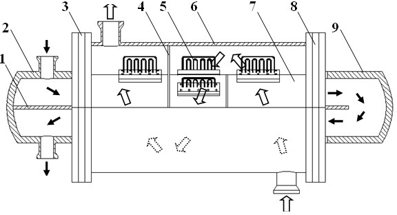
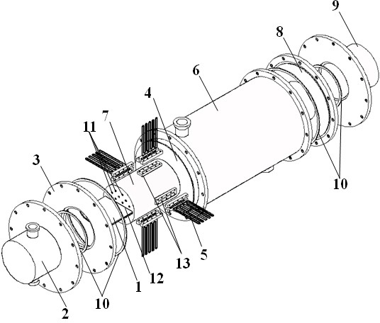
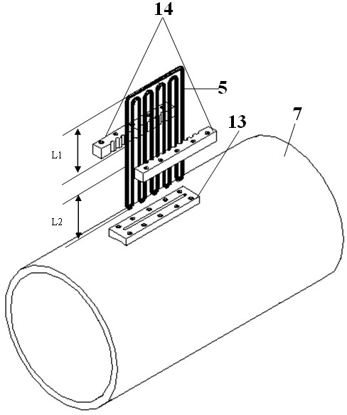
[0024] figure 1 and figure 2 A three-dimensional structure schematic diagram and an assembly schematic diagram of the present invention are provided respectively. It can be seen from the figure that the shell-and-tube pulsating heat pipe heat exchanger proposed by the present invention mainly includes a shell side 6, a tube side 7, sealing flanges 3, 8 and sealing heads 2, 9 arranged at both ends of the shell side. Such as figure 1 and figure 2 As shown, a partition 1 is used in the middle of the tube pass 7 to divide the tube pass 7 into two upper and lower return passages, and the partition plate 1 and the tube pass 7 are connected by expansion joints. 7 Honeycomb holes 11 through which fluid passes and through grooves 12 through which the partition plate 1 passes and is fixed are respectively processed on the wall surfaces at both ends separate...


PUM


Abstract

The invention discloses a tube shell type pulsating heat pipe heat exchanger, which comprises a shell pass, a tube pass, a sealing flange and a sealing head, wherein the sealing flange and the sealing head are arranged at the two ends of the shell pass; the tube pass is arranged in the shell pass and is divided into vertically communicated return fluid passages by a middle partition plate; a sealing flange and a sealing head at the two ends of the tube pass are fixed and hermetically connected with flange rings at the two ends of the shell pass; pulsating heat pipes are arranged on the tube pass and the shell pass; condensation sections of the pulsating heat pipes are positioned in the shell pass; and evaporation sections of the pulsating heat pipes are positioned in the tube pass. According to the tube shell type pulsating heat pipe heat exchanger, the pulsating heat pipes are inserted into the tube shell type heat exchanger in groups, so that the heat exchange space is fully utilized; and a corresponding heat pipe working medium is selected according to the size of a heat flow in a frictional heat exchange process, so that gradient utilization of energy is realized. In addition, the tube shell type pulsating heat pipe heat exchanger can be arranged in any direction and has the advantages of compact structure, small size, simple manufacturing process, convenience for assembly, disassembly and maintenance, no need of an external pump for driving flow, safety in use and excellent application prospect.

Description

technical field [0001] The invention relates to a heat exchange device, in particular to a shell-and-tube pulsating heat pipe heat exchanger designed for high-efficiency cascade utilization of energy. technical background [0002] With the rapid development of the economy, the problem of energy shortage and waste is becoming more and more serious. It is of great engineering significance to adopt active and effective energy-saving and emission-reduction measures for various industrial links involving energy consumption. Shell-and-tube heat exchangers are widely used in various industrial fields such as petrochemical, electric power, environmental protection, and energy due to their advantages of high reliability, compact structure, and simple fabrication. Therefore, optimizing the design or improving the structure of the shell-and-tube heat exchanger to improve its heat exchange efficiency is an important measure for energy saving and emission reduction. [0003] A heat pipe...

Claims


Application Information

Patent Timeline
Patent Type & Authority Applications(China)
IPC IPC(8): F28D15/04
CPCF28D15/0266F28D15/0275
Inventor 陈永平刘向东赵沐雯施明恒
Owner SOUTHEAST UNIV
Learn More