High-precision ultrasonic range-measuring system

A distance measuring system, ultrasonic technology, applied in the direction of radio wave measurement system, sound wave reradiation, measuring device, etc., can solve the problem of failure to detect the return signal of obstacles, the self-excited oscillation of the amplifier circuit, the gain overflow of the signal amplifier circuit, etc. problems, to achieve the effect of improving the accuracy of short-distance measurement, expanding the use, and reducing the distance of blind spots

Active Publication Date: 2012-08-01
CHERY AUTOMOBILE CO LTD
View PDF1 Cites 15 Cited by
  • Summary
  • Abstract
  • Description
  • Claims
  • Application Information

AI Technical Summary

Problems solved by technology

[0003] The traditional ultrasonic return signal detection circuit is directly connected to both ends of the ultrasonic probe, which will bring disadvantages. First, the pulse signal that excites the ultrasonic probe will also enter the return signal detection circuit, which will easily cause the gain of the signal amplifier circuit to overflow, which will cause The amplifier circuit works self-oscillating, and the oscillation time is generally above 5mS. Therefore, during this period of time, the ultrasonic probe cannot detect the return signal of the obstacle due to the self-oscillating oscillation of the amplifier circuit, so it cannot measure the distance of the obstacle. The so-called ultrasonic blind zone, the best known ultrasonic probe can generally control the self-excited oscillation time at 3.5mS, and the corresponding blind zone distance is about 60cm, which greatly limits the application of ultrasonic in short-distance detection

Method used


Image

  • High-precision ultrasonic range-measuring system
  • High-precision ultrasonic range-measuring system
  • High-precision ultrasonic range-measuring system

Examples


Embodiment Construction

[0026] The technical scheme of the present invention is described in detail below in conjunction with accompanying drawing:

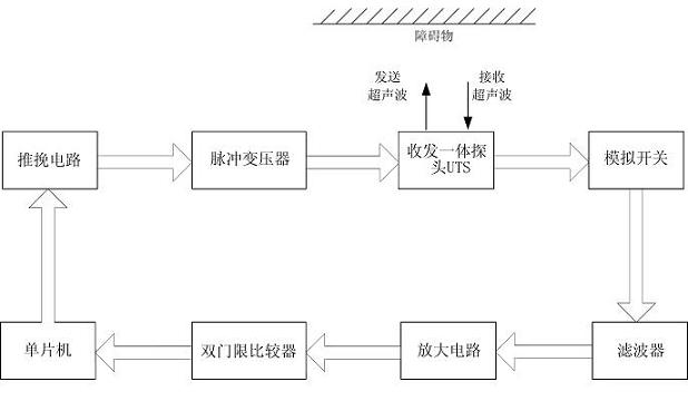
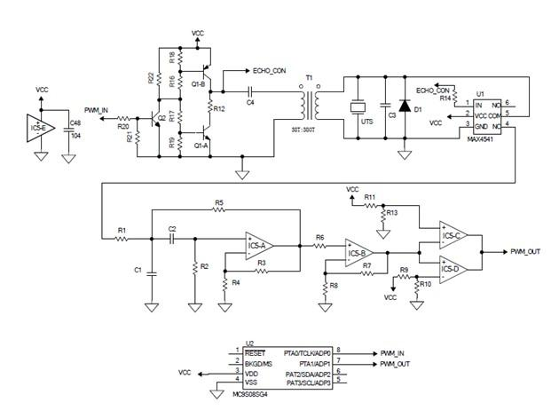
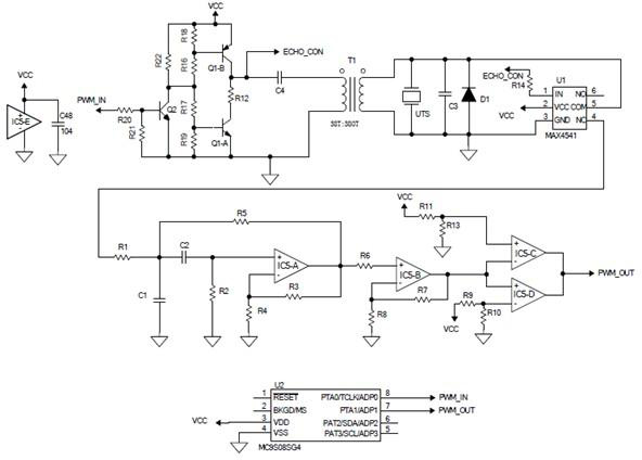
[0027] as attached figure 1 As shown, the ultrasonic ranging system circuit provided by the present invention mainly includes: a push-pull circuit, a pulse transformer T1, an ultrasonic probe UTS integrating transceiver, an analog switch U1, a band-pass filter, a secondary amplifier circuit, a dual-threshold comparator and a single-chip microcomputer, The push-pull circuit is connected to the pulse transformer T1, the output end of the pulse transformer T1 is connected to the ultrasonic probe, the output signal end of the ultrasonic probe is connected to the analog switch U1, the analog switch U1 is connected to the band-pass filter, and the band-pass filter is connected to the two A first-stage amplifying circuit, the second-stage amplifying circuit is connected to the double-threshold comparator, and the double-threshold comparator is connected to the...


PUM


Abstract

The invention provides an ultrasonic range-measuring system which comprises a driving circuit, an ultrasonic probe, a return signal detecting circuit and a singlechip microcomputer, wherein the singlechip microcomputer is connected with the driving circuit, the driving circuit is connected with the ultrasonic probe, a detecting signal of the ultrasonic probe is output to the return signal detecting circuit, an output end of the return signal detecting circuit is connected with the singlechip microcomputer, an analogue switch is further connected between a signal output end of the ultrasonic probe and the return signal detecting circuit, when the singlechip microcomputer sends out a starting signal to the driving circuit, the analogue switch disconnects the connection of the return signal detecting circuit from the range-measuring system, when the singlechip microcomputer stops sending the starting signal to the driving circuit, the analogue switch connects the connection of the returnsignal detecting circuit in the range-measuring system, and the return signal detecting circuit is disconnected when an ultrasonic wave is sent due to the analogue switch with a single-pole double-throw function, so that the self-oscillation caused by the fact that a driving signal is input into a follow-up amplifying circuit can be avoided, and a blind zone detecting distance of the ultrasonic probe can be effectively reduced.

Description

technical field [0001] The invention relates to the field of ultrasonic ranging, and more specifically relates to a high-precision ultrasonic ranging system capable of overcoming blind spots in ranging. Background technique [0002] With the development of science and technology, people are becoming more and more aware of the characteristics of ultrasonic waves, and the wide application of ultrasonic waves has brought a lot of convenience to our lives. Due to the strong directivity of ultrasonic waves, it is often used for distance measurement, and its measurement accuracy can reach millimeter level, so it basically meets the daily use. At present, it has been widely used in automobile safety, such as front and rear reversing radar ranging, blind spot detection system, etc. . [0003] The traditional ultrasonic return signal detection circuit is directly connected to both ends of the ultrasonic probe, which will bring disadvantages. First, the pulse signal that excites the ...

Claims


Application Information

Patent Timeline
Patent Type & Authority Applications(China)
IPC IPC(8): G01S15/08
Inventor 朱得亚邓飞贺周勇
Owner CHERY AUTOMOBILE CO LTD
Why Eureka
Try Eureka