Resistive random access memory unit and resistive random access memory

A resistive memory, random access storage technology, applied in static memory, digital memory information, information storage, etc., can solve the problem of bipolar resistive random access memory not being found, unable to provide enough current, etc., to eliminate the phenomenon of read crosstalk , the effect of reducing the leakage channel

Active Publication Date: 2012-08-01
INST OF MICROELECTRONICS CHINESE ACAD OF SCI
View PDF3 Cites 13 Cited by
  • Summary
  • Abstract
  • Description
  • Claims
  • Application Information

AI Technical Summary

Problems solved by technology

However, the currently reported rectifier diodes only have unidirectional rectification characteristics and cannot provide sufficient current in the opposite direction. Therefore, the current resistive random access memory that can be integrated with rectifier diodes must have unipolar resistance transition characteristics, that is, resistive random access memory. The programming and erasing operations of the memory must be done at the same voltage polarity
However, a suitable rectifier has not been found as a gating tube for the currently common bipolar resistive random access memory.
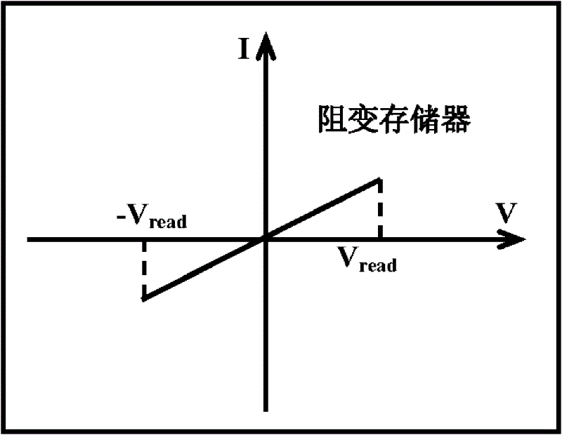
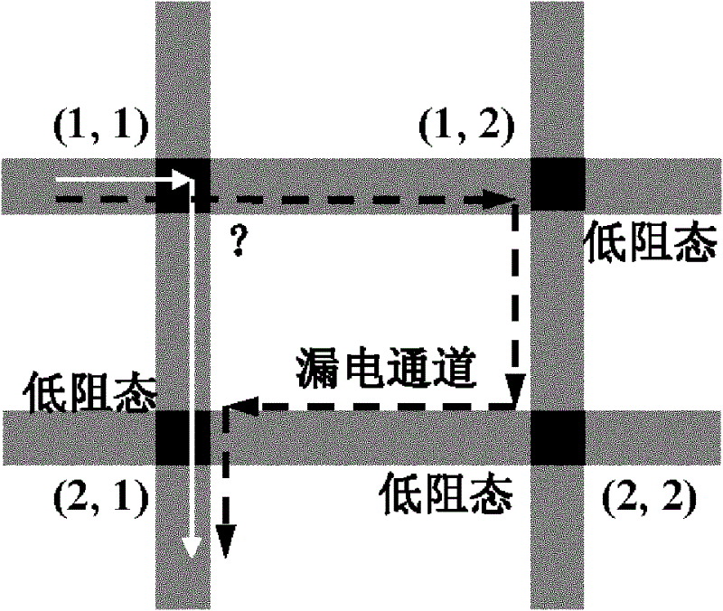
[0006] In the process of realizing the present invention, the inventor realized that the prior art has the following defects: for the bipolar resistive random access memory, no suitable rectifier has been found as its gating tube, resulting in the unavoidable read crosstalk phenomenon

Method used


Image

  • Resistive random access memory unit and resistive random access memory
  • Resistive random access memory unit and resistive random access memory
  • Resistive random access memory unit and resistive random access memory

Examples


Embodiment 1

[0038] Embodiment 1 of the present invention is the unit structure and the design of the read / write mode of the resistive random memory unit composed of a bi-state resistor and a unipolar resistive memory in series.

[0039] Figure 4 It is a current-voltage characteristic curve diagram of a bi-state resistor in a resistive random access memory unit in a DC scanning mode according to an embodiment of the present invention. Such as Figure 4 As shown, the bi-state resistor of this embodiment is initially in a high-impedance state, and when the forward scanning voltage reaches V 1 When the two-state resistor is turned on, the two-state resistor is in a low-impedance state at this time, when the scanning voltage is changed by V 1 to V 2 During retrace, the low resistance state of the bi-state resistor can be maintained, but when the device voltage is less than V 2 , the two-state resistor returns from a low-impedance state to a high-impedance state. Bi-state resistors also h...

Embodiment 2

[0043] Embodiment 2: Another embodiment of the present invention is the design of the cell structure and read / write mode of the resistive non-volatile memory composed of a two-state resistor and a bipolar resistive memory in series.

[0044] In this embodiment, the bi-state resistor has the same current-voltage characteristics as in Example 1.

[0045] Figure 7 It is the current-voltage characteristic curve of the bipolar resistive random access memory in the resistive random access memory unit in the embodiment of the present invention under the DC scanning mode. Such as Figure 7 As shown, the bipolar RRAM in the embodiment of the present invention starts to be in a high-impedance state, and under the forward scanning voltage (using the current limiting mode), when the voltage reaches V set , the RRAM changes from a high-resistance state to a low-resistance state, and when the voltage is removed, the RRAM can still remain in a low-resistance state; unlike Example 1, the e...


PUM


Abstract

The invention discloses a resistive random access memory unit and a resistive random access memory. The resistive random access memory unit comprises a resistive random access memory and a double-state resistor, wherein the resistive random access memory and the double-state resistor are connected in series. A positive electrode and a negative electrode of the double-state resistor all can provide large working currents and thus a leakage passage in an intersection array is reduced so that read crosstalk is eliminated.

Description

technical field [0001] The invention belongs to the technical field of microelectronics and memory, and in particular relates to a resistive variable random memory unit and memory suitable for cross-array integration. Background technique [0002] Resistive Random Access Memory (RRAM), as an emerging non-volatile storage technology, has many advantages in terms of cell area, device density, power consumption, programming / erasing speed, three-dimensional integration and multi-value realization, etc. Compared with FLASH, it has great advantages, and has been highly concerned by large companies and research institutes at home and abroad. The continuous progress of resistive memory technology makes it one of the most powerful competitors for mainstream products in the future non-volatile memory technology market. [0003] The resistive random access memory has a metal / insulator / metal (MIM) vertical device structure, therefore, the resistive random access memory can adopt a cros...

Claims


Application Information

Patent Timeline
Patent Type & Authority Applications(China)
IPC IPC(8): G11C11/56
CPCH01L27/2409H01L45/04G11C2213/77G11C2213/75G11C11/56G11C13/0002H01L45/14H01L45/1253G11C13/0007G11C13/003H10B63/20H10N70/20H10N70/841H10N70/881
Inventor 刘琦刘明龙世兵吕杭炳
Owner INST OF MICROELECTRONICS CHINESE ACAD OF SCI
Why Eureka
Try Eureka