Charging-discharging control circuit of vehicular power battery pack

A power battery pack, charge and discharge control technology, applied in the direction of battery circuit devices, circuit devices, collectors, etc., can solve the problems of difficult to achieve fast charging of battery packs, rapid increase in failure rate of power supply systems, and low reliability of battery pack systems , to achieve the effect of improving safety and reliability, low requirements, and high safety and reliability

Inactive Publication Date: 2012-08-01
GUANGXI UNIV
View PDF5 Cites 14 Cited by
  • Summary
  • Abstract
  • Description
  • Claims
  • Application Information

AI Technical Summary

Problems solved by technology

If the battery pack is discharged by connecting all battery cells in series, the reliability of the entire battery pack system is not high, the service life of the battery pack is not long, and the failure of the battery cell will directly affect the normal operation of the entire power system, which may cause As a result, the failure rate of the power supply system increases rapidly; if the battery pack is discharged in a full parallel connection of battery cells, the voltage value required by the external motor and other equipment will not be reached. When this connection method is used for fast charging, the internal cables of the battery pack It needs to withstand a considerable current, and it is also not conducive to the development of charging equipment; if the battery pack is charged in a series-parallel hybrid connection of battery cells, it is difficult to achieve fast charging of the battery pack with high voltage and low current

Method used


Image

  • Charging-discharging control circuit of vehicular power battery pack
  • Charging-discharging control circuit of vehicular power battery pack
  • Charging-discharging control circuit of vehicular power battery pack

Examples


Embodiment Construction

[0020] The present invention will be further described below in conjunction with accompanying drawing.

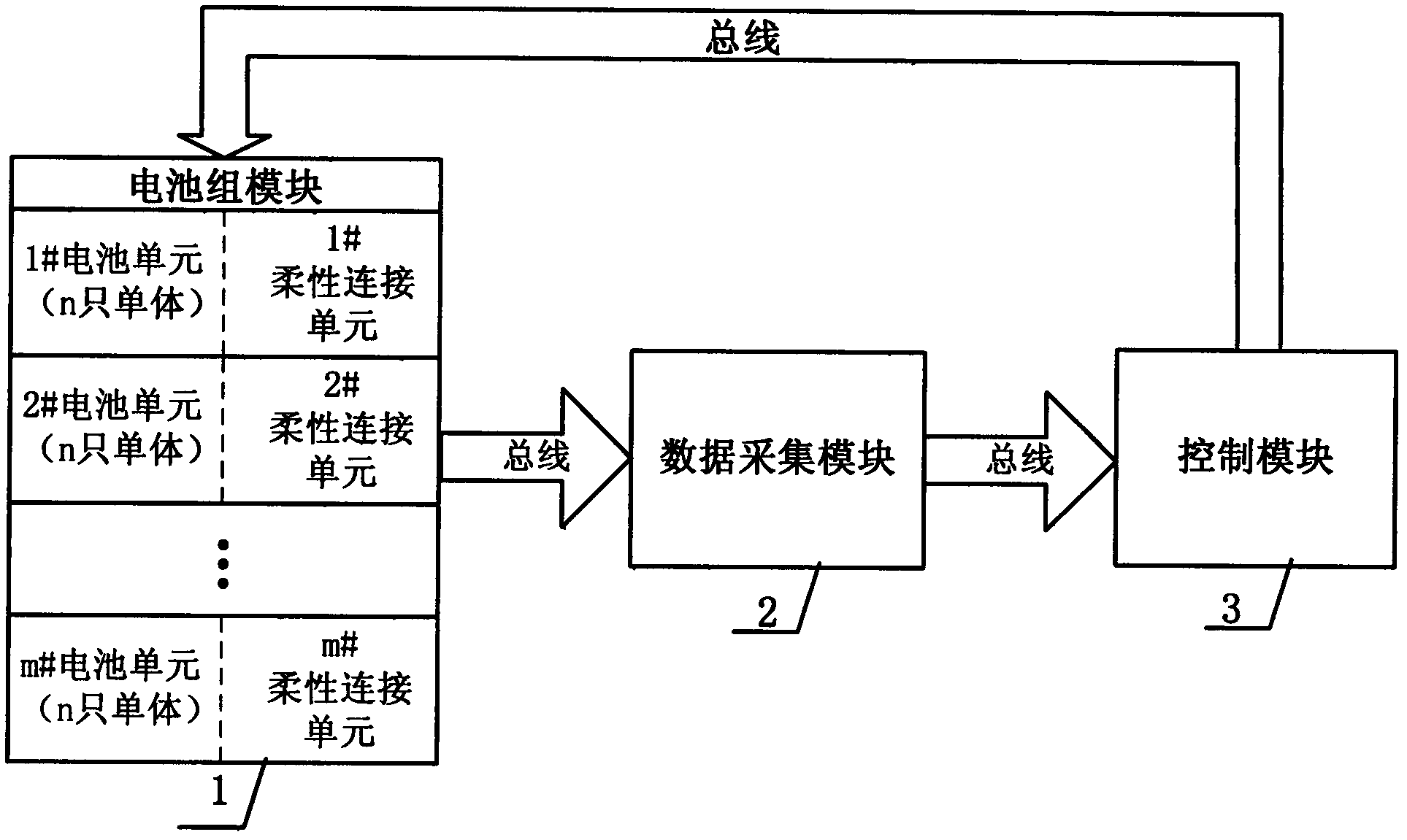
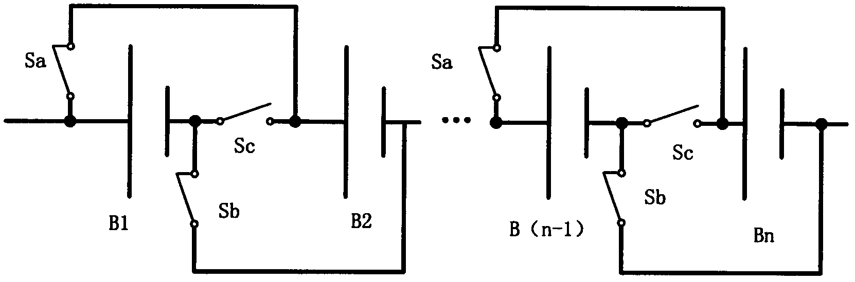
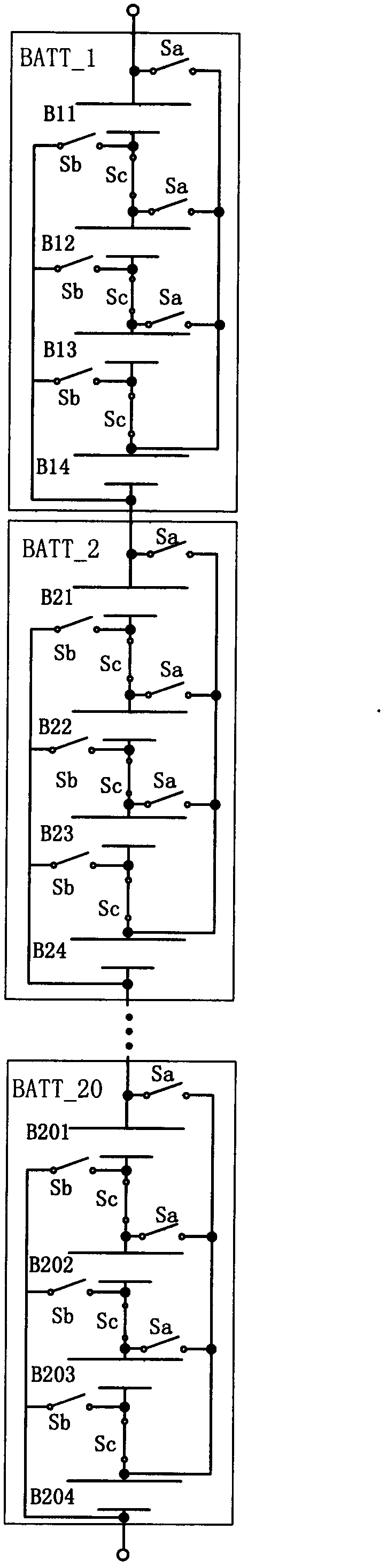
[0021] Schematic diagram of the structure of the flexible connection system of the vehicle power battery pack of the present invention, as shown in figure 1 As shown, the control module 3 sends the action control signal of the automobile relay to the battery flexible connection unit in the flexible connection battery pack module 1, drives the automobile relay in the flexible connection unit in the flexible connection battery pack module 1 to act, and the action of the automobile relay , realizing switching between the series state and the parallel state between the battery cells in the battery cells in the flexible connection battery pack module 1 .

[0022] The data acquisition module 2 measures the voltage of the battery cells in the battery cells in the flexible connection battery module 1, the temperature of the battery cells, the total current value of the flexible con...


PUM


Abstract

The invention discloses a charging-discharging control circuit of a vehicular power battery pack, which at least comprises a flexible connection battery pack module 1, a data acquisition module 2 and a control module 3, wherein the flexible connection battery pack module 1 at least comprises a battery unit and a flexible connection unit. The charging-discharging control circuit disclosed by the invention realizes switching of single battery connection modes of the vehicular power battery pack under the charging and discharging conditions; when the vehicular power battery pack is charged, all single batteries are charged in a series connection mode, therefore low-current fast charging under high voltage is realized easily, and the charging speed is improved; when the vehicular power battery group is in a discharging state, the single batteries are connected in parallel and then connected in series, and thus the fault rate of the whole battery pack system is reduced; and the control circuit disclosed by the invention can ensure that the consistency of the single batteries in the battery unit is kept well, the optimal property of each single battery is expressed, the battery volume is fully utilized, the life of the battery pack is prolonged, and favorable practical application value is achieved.

Description

technical field [0001] The invention relates to the field of electric vehicles and the field of battery management systems, in particular to a charging and discharging control circuit for a vehicle power battery pack. Background technique [0002] At present, energy shortage and environmental pollution are important reasons restricting the sustainable development of human beings. They are two major challenges to the development of the world's automobile industry. In the process of research and development of electric vehicles, power batteries and their management systems are used as power sources and auxiliary power sources. Components are the most important part. In order to ensure the good performance of the battery and prolong the service life of the power battery, a special management system must be set up to detect its working status and manage and control it reasonably and effectively, so as to cooperate with the normal control system to realize the complete vehicle. S...

Claims


Application Information

Patent Timeline
Patent Type & Authority Applications(China)
IPC IPC(8): H02J7/00
Inventor 陈琳潘海鸿林伟龙黄弋哲黄毅崇陈健平侯志广
Owner GUANGXI UNIV
Why Eureka
Try Eureka