Permanent magnetic coupling transmission, braking or load device with cooling and lubricating device

A technology of permanent magnetic coupling and lubrication device, which is applied in the direction of permanent magnetic clutch/brake, cooling/ventilation device, electromechanical device, etc., and can solve the problem that the lubrication problem of permanent magnetic coupling components cannot be effectively solved.

Inactive Publication Date: 2012-08-01
林贵生
View PDF11 Cites 117 Cited by
  • Summary
  • Abstract
  • Description
  • Claims
  • Application Information

AI Technical Summary

Problems solved by technology

[0012] In summary and in conjunction with the actual difficulties we encountered in the implementation and promotion of the above-mentioned patents, there are two problems to be solved urgently: on the one hand, the problems in the known permanent magnetic coupling and speed regulation technical solutions are high power ( 500-3000 kilowatts) and ultra-high power (greater than 3000 kilowatts) transmission shaft permanent magnetic coupling drive and technical solutions for speed control devices still have a large technical bottleneck, specifically the heat dissipation and cooling of the heat-generating components of the permanent magnetic coupling assembly problems and the lubrication problems in the transmission components and adjustment mechanisms in the system have not been effectively resolved; on the other hand, the innovative application and development of permanent magnet coupling drive and speed regulation technology in some traditional technical fields are still blank, especially for transmission shaft coupling. Transmission and its load speed regulation and cutting/combining CVTs, clutches, turbofan stepless speed regulation devices in aircraft and propeller stepless spe

Method used


Image

  • Permanent magnetic coupling transmission, braking or load device with cooling and lubricating device
  • Permanent magnetic coupling transmission, braking or load device with cooling and lubricating device
  • Permanent magnetic coupling transmission, braking or load device with cooling and lubricating device

Examples


Embodiment 1

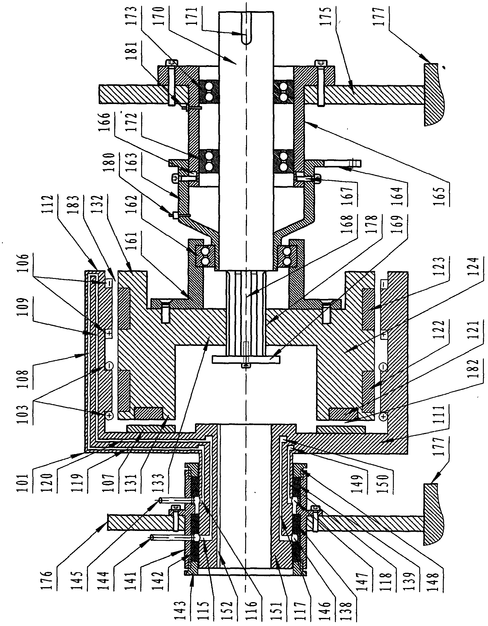
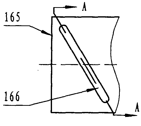
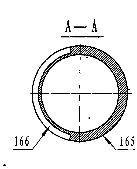
[0072] Such as figure 1 , figure 2 and image 3 As shown, it is "axial magnetic field + radial magnetic field + radial magnetic field" single-layer series-connected three sets of permanent magnetic coupling components. Magnetic field permanent magnetic coupling components (axial magnetic field circular metal conductor type permanent disk 107, axial magnetic field circular permanent magnetic disk 121) and two sets of radial magnetic field permanent magnetic coupling components (radial magnetic field cylindrical armature winding disk 103 , radial magnetic field cylindrical permanent disk 122, radial magnetic field cylindrical squirrel cage armature disk 106, radial magnetic field cylindrical permanent magnetic disk 123), a pair of active rotor disk (111) and rotating cylinder in the permanent magnetic coupling assembly (112) The matching active rotor disk coupling mechanism (151) and the corresponding driving shaft coupling mechanism (152), a pair of passive rotor disk (131) ...

Embodiment 2

[0077] Such as Figure 4 As shown, it is a "radial magnetic field + radial magnetic field" two-layer permanent magnetic coupling coupling with two sets of permanent magnetic coupling components nested drum structure, which consists of two sets of radial magnetic field permanent magnetic coupling components (one set is A permanent magnetic coupling assembly composed of a radial magnetic field cylindrical metal conductor armature disk 207 and a radial magnetic field cylindrical permanent disk 221. The cylindrical permanent disk 221 is nested with a metal conductor armature disk 203 and a radial magnetic field cylindrical permanent disk. 221 constitutes another set of permanent magnetic coupling assemblies), a pair of active drum coupling mechanisms (201, 211, 251) adapted to the active drums (212, 213) in the permanent magnetic coupling assembly and corresponding active Shaft coupling mechanism (253, 284, 276), a pair of passive drum coupling mechanism (passive drum body 233, sp...

Embodiment 3

[0081] Such as Figure 5As shown, it is a permanent magnetic coupling coupling of "radial magnetic field + radial magnetic field" two layers in series with four sets of permanent magnetic coupling components nested drum composite structure, consisting of four sets of radial magnetic field permanent magnetic coupling components ( The permanent magnetic coupling assembly composed of the radial magnetic field cylinder-type mouse dragon type armature disk 303 and the radial magnetic field cylindrical type permanent disk 322 is connected in series with the permanent magnetic coupling assembly composed of the mouse dragon type armature disk 306 and the permanent disk 323, embedded The permanent magnet coupling assembly that the winding armature disk 304 and the permanent magnetic disk 322 constitute are connected in series (the permanent magnetic coupling assembly composed of the winding armature disk 305 and the permanent magnetic disk 323), one pair and the driving drum (312, 302) ...


PUM


Abstract

The invention relates to a permanent magnetic coupling transmission, braking or load device with a cooling and lubricating device. The permanent magnetic coupling transmission, braking or load device is in a structure of a rotor disc, a rotating cylinder or in a combined/composite structure of the rotor disc and the rotating cylinder. The permanent magnetic coupling transmission, braking or load device consists of at least one group of axial magnetic field or/and radial magnetic field permanent magnetic coupling modules, at least one pair of a driving rotor disc/rotating cylinder coupling mechanism and a driving shaft coupling mechanism, at least one pair of a driven rotor disc/rotating cylinder coupling mechanism and a driven shaft coupling mechanism, one pair of air-gap space and coupling area adjusting mechanisms, at least one set of coolant cooling devices, at least one set of lubricating devices, at least one pair of integrated assembling mechanisms facilitating integration of system structure and a shell. The permanent magnetic coupling transmission, braking or load device is suitable for the technical fields such as transmission, speed regulation of transmission shaft and load, braking, rotating load, energy conservation and emission reduction, disconnection/connection power and the like. The invention is used for designing a technical scheme of a permanent magnetic coupling device, a speed regulation coupler device, automatic speed changing device, a brake device, a load/loading device, a centrifugal load speed regulation device or an engaging-disengaging device.

Description

technical field [0001] The technical fields involved in the present invention include: the technical field of transmission shaft coupling drive and speed regulation, the technical field of energy saving and emission reduction, the technical field of cutting / combining power, the technical field of braking, the technical field of loading / loading of power equipment dynamometer, especially a A permanent magnet coupling drive, brake or load device with cooling and lubricating devices. Background technique [0002] Around us, there are many systems or devices related to the coupling transmission between the power equipment output shaft and the load input shaft and its load speed regulation technology, the rotation braking technology, the power equipment dynamometer and its simulated load technology. And there are serious technical defects and deficiencies, for example as follows: [0003] 1. Drive shaft coupling drive and speed regulation technical field: ①The hydraulic coupling / ...

Claims


Application Information

Patent Timeline
IPC IPC(8): H02K51/00H02K49/10H02K9/00
Inventor 林贵生余亚莉
Owner 林贵生
Why Eureka
Try Eureka