Spiral flow whirlwind gas separator

A gas separator and cyclone technology, which is applied in separation methods, dispersed particle separation, chemical instruments and methods, etc., can solve the problems of gas concentration and enrichment that are not ideal, and achieve the effect of compact structure and high separation efficiency.

Inactive Publication Date: 2012-08-08
陈启东 +1
View PDF10 Cites 7 Cited by
  • Summary
  • Abstract
  • Description
  • Claims
  • Application Information

AI Technical Summary

Problems solved by technology

However, the gas separator with this structure is still not ideal for the concentration and enrichment o

Method used


Image

  • Spiral flow whirlwind gas separator
  • Spiral flow whirlwind gas separator
  • Spiral flow whirlwind gas separator

Examples


Embodiment Construction

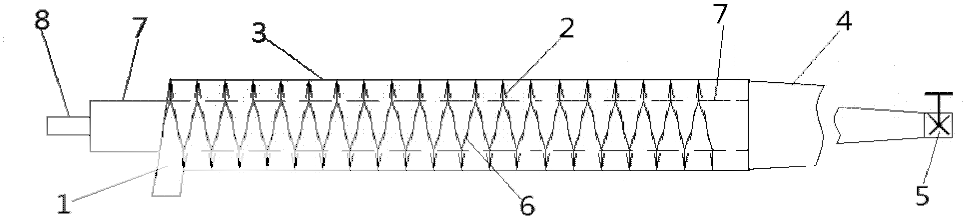
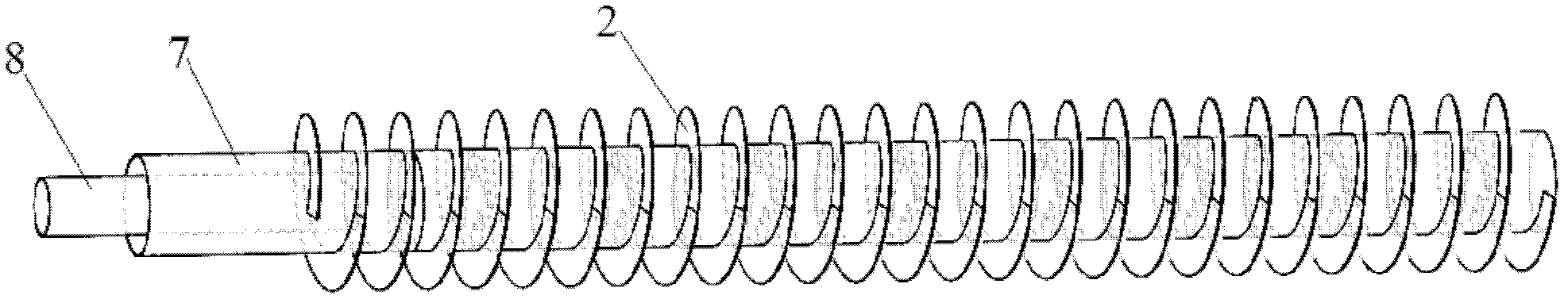
[0020] like figure 1 , 2 As shown in and 5, the spiral flow cyclone gas separator includes an outer spiral flow path formed by the outer pipe 3 and the outer spiral piece 2 in the outer pipe 3, and the two ends of the outer spiral flow path are respectively provided with an inlet 1 and an outlet.

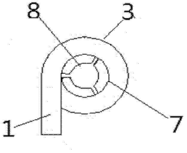
[0021] like image 3 , 4 As shown, an inner pipe 7 is also arranged in the outer pipe 3, the inner pipe 7 and the inner spiral piece 6 arranged inside the inner pipe 7 form an inner spiral flow path, and the flow of gas in the outer spiral flow path and the inner spiral flow path The direction is opposite, so as to meet the purpose of collecting gas at one end of inlet 1.

[0022] At the outlet of the inner pipeline 7, a collection pipe 8 is arranged at the inner center of the inner pipeline 7 (ie, the axis of the inner pipeline 7); at the outlet of the outer pipeline 3, a tapered cyclone flow channel 4 is connected to the outer pipeline 3. The collecting pipe 8 may not be at th...


PUM

PropertyMeasurementUnit
Diameteraaaaaaaaaa
Diameteraaaaaaaaaa
Diameteraaaaaaaaaa

Abstract

The invention discloses a spiral flow whirlwind gas separator. The spiral flow whirlwind gas separator comprises an outer spiral runner which consists of an outer pipeline (3) and outer spiral blades (2) in the outer pipeline (3), and both ends of the outer spiral runner are respectively provided with an inlet (1) and an outlet. The spiral flow whirlwind gas separator is characterized in that the interior of the outer pipeline (3) is also provided with an inner pipeline (7); the inner pipeline (7) and inner spiral blades (6) arranged in the inner pipeline (7) form an inner spiral runner; the flow directions of gas in the outer spiral runner and gas in the inner spiral runner are opposite; a collecting pipe (8) is arranged at the outlet of the inner pipeline (7) in the inner pipeline (7); and the outlet of the outer pipeline (3) is connected with a conical whirlwind runner (4). Two layers of spiral blades with different sizes and screw pitches are contained in the spiral flow whirlwind gas separator. At a very high spiral speed, the primary separation and the secondary separation of methane and air are realized by utilizing the principle of density contrast between the methane and the air, and finally, the density of gas discharged into the air is reduced, and the purification and the secondary utilization of the gas are realized, and the separation efficiency is high.

Description

technical field [0001] The invention relates to a gas separator, in particular to a spiral flow cyclone type gas separator. Background technique [0002] The natural and convective buoyancy of methane gas in the air is a well-known natural phenomenon. The research on the stratified flow of multiple mixed fluids is based on the continuity equation, turbulent flow equation and diffusion equation of fluid mechanics, and the turbulent energy equation and state equation are added for complex flows. [0003] The domestic patents related to gas enrichment mainly include: ZL 200520024727.X, which is called the gas accumulation control device in the coal bunker of the coal preparation plant, and the patent number is ZL200810236122.5, and the patent name is the low-concentration gas heat convective buoyancy collection device. Based on the domestic and foreign research on the density stratified flow of multi-component mixed gas, especially the stratified flow of low-concentration gas ...

Claims


Application Information

Patent Timeline
IPC IPC(8): B01D53/24
Inventor 陈启东马利江左志全
Owner 陈启东
Why Eureka
Try Eureka