Supercharge Your Innovation With Domain-Expert AI Agents!

High pressure guide vane carrier ring processing technology

A processing technology and a technology for guide vanes, which are applied in the field of high-pressure guide vane ring-holding processing technology, can solve the problems of difficult processing of high-pressure guide vane rings, difficult processing of steam extraction grooves, complicated extraction groove profiles, etc. The effect of improved quality and high material utilization

Active Publication Date: 2014-07-02
SHANGHAI ELECTRIC POWER GENERATION EQUIPMENT CO LTD
View PDF5 Cites 0 Cited by
  • Summary
  • Abstract
  • Description
  • Claims
  • Application Information

AI Technical Summary

Problems solved by technology

[0004] 2. It is very difficult to process the inner cavity plane groove and steam extraction groove of the high-pressure guide vane holding ring; in the process of processing, the elongation of the ram needs to be greater than 1700mm, but the rigidity of the ram is poor, which will affect the processing accuracy. Difficulties; the shape of the steam extraction groove is complex, the entrance is small, difficult to process, and the requirements for the tool are high;
[0005] 3. On the outer end surface of the large inner cavity of the high-pressure guide vane holding ring, there are two 1800mm deep blind holes with a diameter of φ65 that need to be processed, and they need to be connected with a 90-degree connection hole, which is relatively difficult to process;
Therefore, it is necessary to fully consider how to control the thermal deformation, so as to ensure the precision size of the workpiece during processing and reduce the deformation of the workpiece during processing. The above factors have caused the problem that the processing of the high-pressure guide vane holding ring is difficult.

Method used


Image

  • High pressure guide vane carrier ring processing technology
  • High pressure guide vane carrier ring processing technology
  • High pressure guide vane carrier ring processing technology

Examples


specific Embodiment approach

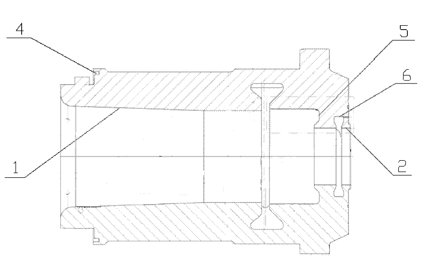
[0064] A specific embodiment of the high-pressure guide vane holding ring processing technology of the present invention includes the following steps:

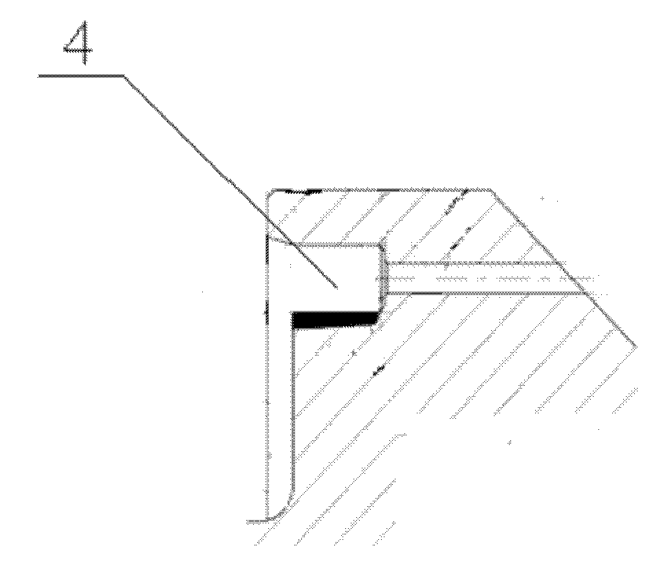
[0065] 1) Roughly machining the surfacing welding plane groove 4 by means of milling, and then finishing machining the surfacing welding plane groove 4 by means of turning;

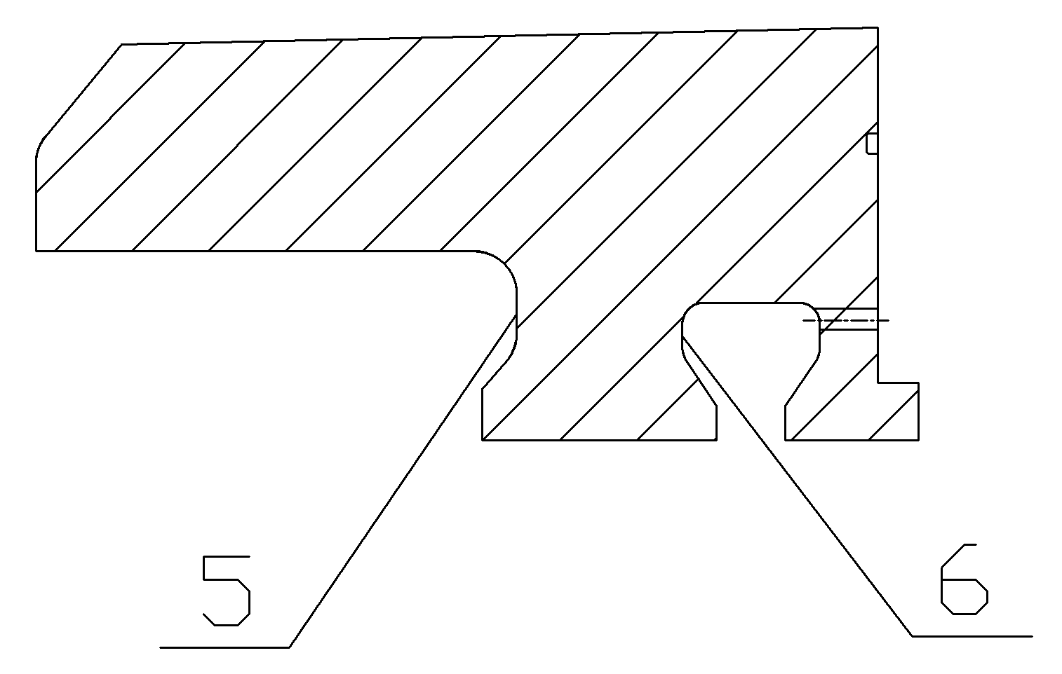
[0066] 2) According to the shape of the inner cavity plane groove 5 and the steam extraction groove 6, the inner cavity plane groove 5 and the steam extraction groove 6 are processed through the numerical control program;

[0067] 3) Processing deep blind hole 3;

[0068] 4) Process the vane groove 7.

[0069] A kind of specific implementation of the processing technology of deep blind hole 3, comprises the following steps:

[0070] 1) Establish a processing model according to the position of the connecting hole 9, and edit the numerical control positioning program;

[0071] 2) Drill a pilot hole to locate the position of the deep blind hole 3;

[007...


PUM


Abstract

The invention relates to a high pressure guide vane carrier ring processing technology. The processing technology comprises the following steps: 1) a surfacing planar slot is roughly machined by employing a milling mode, and then the surfacing planar slot is finely finished by employing a turning mode; 2) an intracavity planar slot and a steam extraction groove are processed through a numerical control program according to shapes of the intracavity planar slot and the steam extraction groove; 3) a deep blind hole is processed; and 4) a static blade groove is processed. By adopting the processing technology in the invention, a processing quality of the high pressure guide vane carrier ring is greatly improved, an efficiency of gas turbine combined cycle unit is directly improved, and then a generating efficiency is improved; and a precision of parts is effectively improved, a quality of products manufacturing is guaranteed, and a processing efficiency is improved, providing a stable working quality and a high working efficiency of the high pressure guide vane carrier ring under the conditions of high temperature, high speed, impact and shock, and simultaneously providing a high utilization rate, a long service life and a greatly reduced cost.

Description

technical field [0001] The invention relates to a high-pressure guide vane holding ring processing technology. Background technique [0002] The high-pressure guide vane holding ring is one of the components of the gas turbine combined cycle steam turbine, and is the core component of the combined cycle steam turbine. Its quality will directly affect the working efficiency of the combined cycle unit, so it is very important to ensure the quality of the high-pressure guide vane holding ring. The high-pressure guide vane holding ring to be processed in the present invention adopts the split structure of the upper and lower half, and there are Φ65×1800mm deep blind holes and surfacing plane grooves on the end face; there are inner cavity plane grooves, steam extraction grooves, 28 levels in the inner cavity Composition of vane slots. The specific structure is as Figure 1 to Figure 6 As shown, the high-pressure guide vane holding ring includes an inner cavity, and the inner ca...

Claims


Application Information

Patent Timeline
Patent Type & Authority Patents(China)
IPC IPC(8): B23P15/00
Inventor 沈永根蔡振铭周辉峰董桔花
Owner SHANGHAI ELECTRIC POWER GENERATION EQUIPMENT CO LTD
Features
  • R&D
  • Intellectual Property
  • Life Sciences
  • Materials
  • Tech Scout
  • Unparalleled Data Quality
  • Higher Quality Content
  • 60% Fewer Hallucinations
Learn More