Automatic torsion bar press fitting, measuring and straightening equipment

A straightening and equipment technology, applied in force/torque/work measuring instruments, measuring devices, metal processing equipment, etc., can solve the problems that a single equipment cannot meet the takt time requirements of automated assembly lines, the equipment structure is complex, and the process takt time is long. , to achieve the effect of short process cycle, high equipment integration and easy adjustment of process parameters

Active Publication Date: 2012-08-08
WUHU HIT ROBOT TECH RES INST
View PDF5 Cites 23 Cited by
  • Summary
  • Abstract
  • Description
  • Claims
  • Application Information

AI Technical Summary

Problems solved by technology

[0003] The purpose of the present invention is to provide a torsion bar automatic press-fitting, measurement and straightening equipment to solve the problems of cumbersome process, complicated equipment structure, high price, long process cycle and short production cycle when the process of torsion bar connected with the automobile steering wheel is complicated. The problem that one piece of equipment cannot meet the tact requirements of the automated assembly line

Method used


Image

  • Automatic torsion bar press fitting, measuring and straightening equipment
  • Automatic torsion bar press fitting, measuring and straightening equipment
  • Automatic torsion bar press fitting, measuring and straightening equipment

Examples


specific Embodiment approach 1

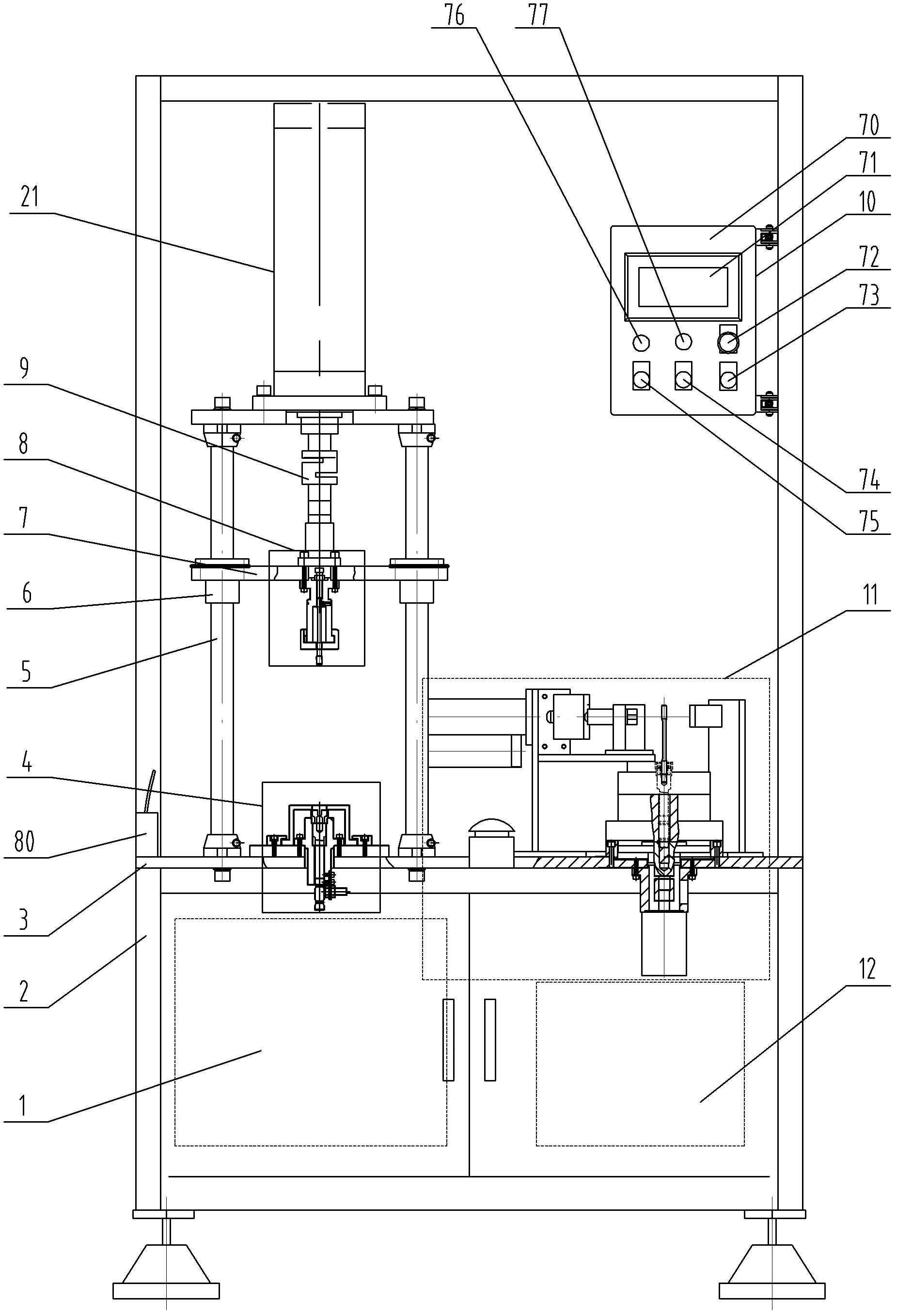
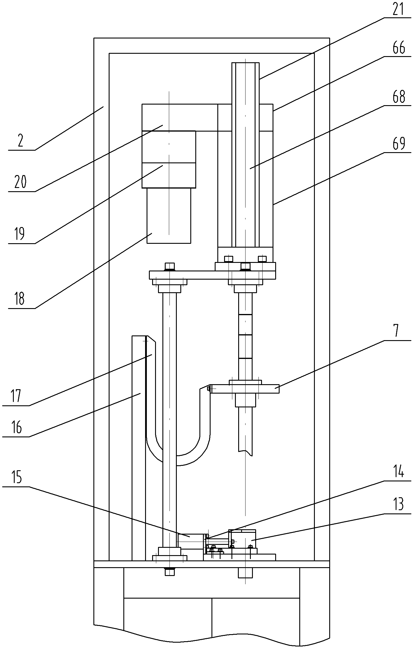
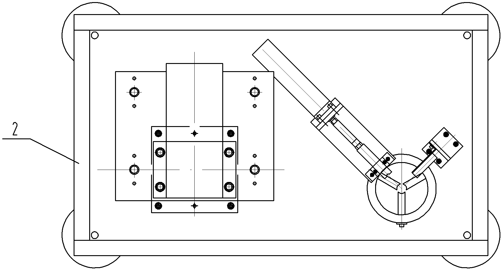
[0008] Specific implementation mode one: combine Figure 1-Figure 7 Explain that the torsion bar automatic press-fitting, measuring and straightening equipment of this embodiment includes an electric control system mounting plate 1, a frame 2, a platen 3, a lower clamp 4, a slide plate 7, an upper clamp 8, and a tension sensor 9. Man-machine interface component 10, measuring alignment mechanism 11, pneumatic system connecting plate 12, cylinder support 14, cylinder 15, first support 16, drag chain 17, press-fit AC servo motor 18, press-fit reducer 19, press-fit Install the synchronous belt transmission mechanism 20, the press-fit linear motion mechanism 21, four guide shafts 5 and four linear bearings 6, the press-fit linear motion mechanism 21 includes a press-fit screw 68 and a press-fit jacket 69;

[0009] The platen 3 is arranged horizontally and fixedly connected with the frame 2, the platen 3 is provided with a first through hole, the lower clamp 4 is arranged at the fir...

specific Embodiment approach 2

[0010] Specific implementation mode two: combination figure 1 , Figure 4 and Figure 5 Explain that the upper clamp 8 of this embodiment includes a tension cap 23, an upper clamp body 24, a bearing sleeve 25, an adjusting screw 26, a spring coil 27, a top post 28 and a steel ball 29;

[0011] The middle part of the upper end of the upper clamp body 24 is provided with a threaded hole, and the middle part of the lower end of the upper clamp body 24 is provided with an open inner cavity. In the open inner cavity of the clamp body 24, the lower end of the upper clamp body 24 is inserted in the tension cap 23 (quick connection can be realized), and the load-bearing sleeve 25 and the tension cap 23 are all provided with mounting holes, and the load-bearing sleeve 25 and The mounting holes of the tension cap 23 are coaxially arranged with the threaded hole and the connection hole of the upper clamp body 24, the adjusting screw 26 is threaded with the threaded hole of the upper cl...

specific Embodiment approach 3

[0012] Specific implementation mode three: combination figure 1 , Figure 4 and Image 6 Explain that the lower clamp 4 of this embodiment includes a proximity switch 30, a proximity switch bracket 31, a lower clamp body 33, a bearing plate 34, a slider 13 and an adjustment plate 35;

[0013] The adjustment plate 35 is fixedly connected with the upper end surface of the platen 3, the adjustment plate 35 is provided with a third through hole communicating with the first through hole of the platen 3, the outer wall of the lower clamp body 33 is provided with a boss, and the lower clamp body 33 The lower end of the lower end of the adjustment plate 35 and the first through hole of the platen 3 are sequentially pierced, and the boss of the lower clamp body 33 is affixed to the upper end surface of the adjustment plate 35. The position in the height direction is adjustable, the proximity switch 30 is connected with the proximity switch bracket 31, the proximity switch bracket 31 ...


PUM


Abstract

The utility model relates to torsion bar press fitting and measuring straightening equipment, in particular to automatic torsion bar press fitting, measuring and straightening equipment, aiming to solve the problem that single equipment cannot meet a pace requirement when a torsion bar processing process is complicated, torsion bar processing equipment is complicated in structure and high in price, the process pace is long and the production pace is short. A bedplate is fixedly connected with a machine frame; a lower clamp and a guide shaft are fixedly connected with the bedplate; a linear bearing is installed on the guide shaft; a sliding plate is fixedly connected with the linear bearing; an upper clamp and a pull pressure sensor are fixedly connected with the sliding plate; a measuring and straightening mechanism and a cylinder support are fixedly connected with the bedplate; a cylinder is fixedly connected with the cylinder support; a cylinder rod of the cylinder is fixedly connected with a slide block inside the lower clamp; a first support is fixedly connected with the bedplate; a drag chain is fixedly connected with the first support and the sliding plate; a press-fitting alternating current servo motor is in transmission connection with a press-fitting speed reducer; the press-fitting speed reducer is in transmission connection with a press-fitting synchronous belt transmission mechanism; the press-fitting synchronous belt transmission mechanism is in threaded connection with a press-fitting screw rod; and the press-fitting screw rod is fixedly connected with the pull pressure sensor. The automatic torsion bar press fitting, measuring and straightening equipment is used for automatic press fitting, measuring and straightening of a torsion bar.

Description

technical field [0001] The invention relates to a torsion bar pressing, measuring and straightening device, which belongs to the technical field of automobile steering systems. Background technique [0002] In the automobile steering system, the processing quality of the torsion bar will directly affect the steering performance of the automobile and the comfort of the driver. At present, the processing method commonly used in the industry is: torsion bar and connecting shaft are transitionally fitted, and the radial direction is used as a connecting pin after assembly. There is following shortcoming in this method: 1. technology is loaded down with trivial details, need punching center hole, drilling, reaming, deburring, dress pin, press pin. 2. The equipment structure is complicated and the price is high. 3. When the process beat is long and the production beat is short, a single device cannot meet the beat requirements of an automated assembly line. Contents of the inv...

Claims


Application Information

Patent Timeline
Patent Type & Authority Applications(China)
IPC IPC(8): B23P19/02B23P19/10G01L5/00G01B11/00
Inventor 高云峰李瑞峰程志千
Owner WUHU HIT ROBOT TECH RES INST
Why Eureka
Try Eureka