Dynamic distribution system of gaseous methyl iodine

A methyl iodide, dynamic technology, applied in the environment, medicine, and chemical industry, can solve the problems of unsuitable for long-term continuous use, complex structure, complex process, etc., and achieve long-term continuous and stable supply, easy to achieve, and stable concentration.

Active Publication Date: 2012-08-08
CHINA NUCLEAR POWER ENG CO LTD
View PDF5 Cites 2 Cited by
  • Summary
  • Abstract
  • Description
  • Claims
  • Application Information

AI Technical Summary

Problems solved by technology

The current conventional method is to use high-purity nitrogen to prepare high-pressure gaseous methyl iodide with the required concentration and store it in a pressure cylinder, and then send it to the gas environment by the pressure cylinder. The concentration of methyl iodide gas obtained by this method is accurate and stable, but there are Major disadvantages: Firstly, the process is complicated and the cost is too high, so it is not suitable for continuous use for a long time; in addition, for the working conditions where the distribution concentration changes frequently and the change range is large, the above method is difficult to meet the requirements
In order to ensure the stability of gaseous methyl iodide distribution concentration, the liquid supply system of methyl iodide requires that it can be constant for a long time under different supply flow rates, especially small flow rates, and the flow rate can be continuously adjusted. A method for solving the above problems in related fields is in Patent No. 86200978 discloses that a stable flow rate of several milliliters per minute can be obtained according to the method. However, the method is relatively complicated in structure, uses a computer as a control tool, and requires electric drive. It is expected to obtain a simple structure, relying on Passive feedback regulation to achieve long-term stable liquid supply device with small flow rate

Method used


Image

  • Dynamic distribution system of gaseous methyl iodine
  • Dynamic distribution system of gaseous methyl iodine
  • Dynamic distribution system of gaseous methyl iodine

Examples


Embodiment Construction

[0017] The present invention is described in more detail below in conjunction with accompanying drawing example:

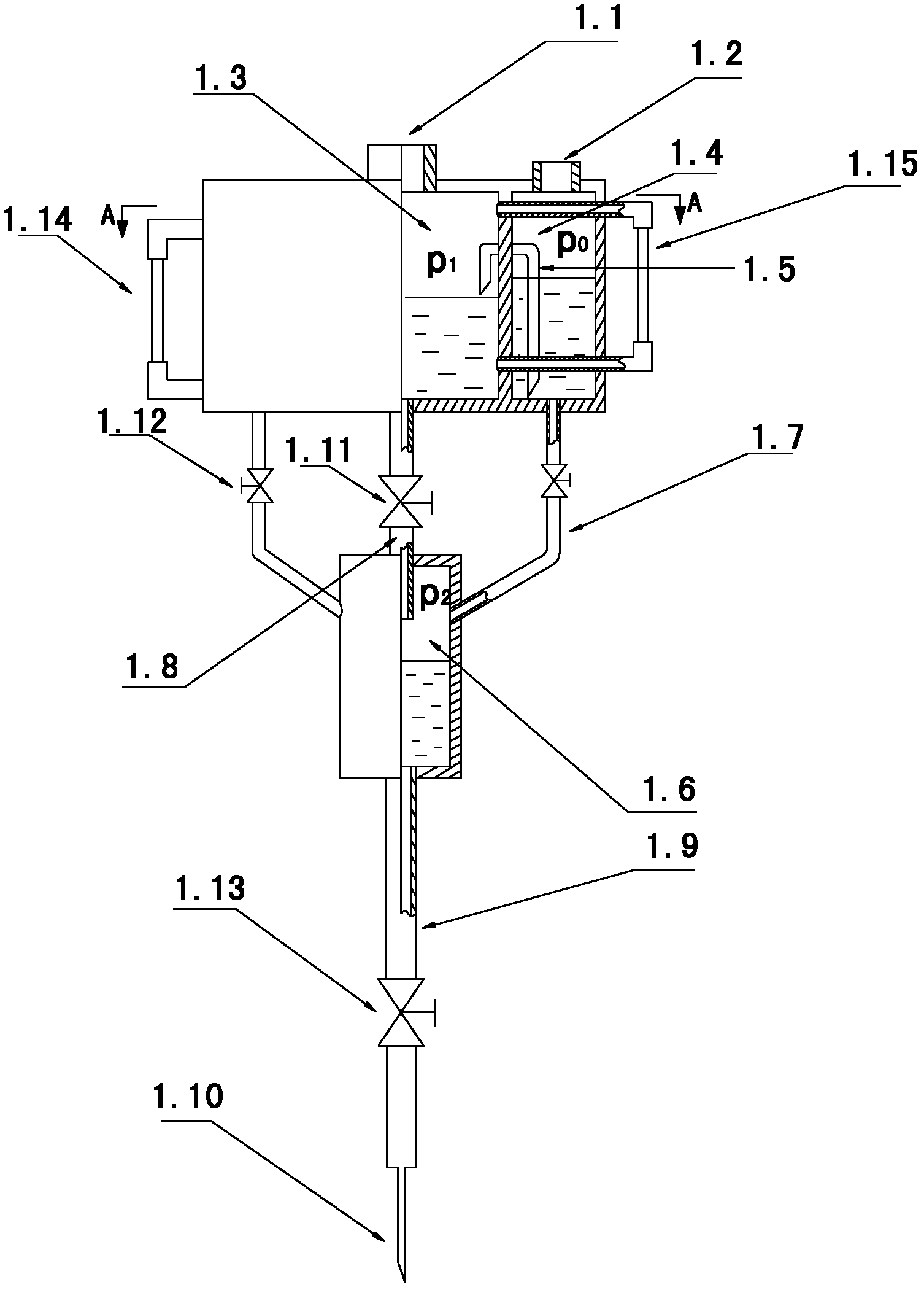
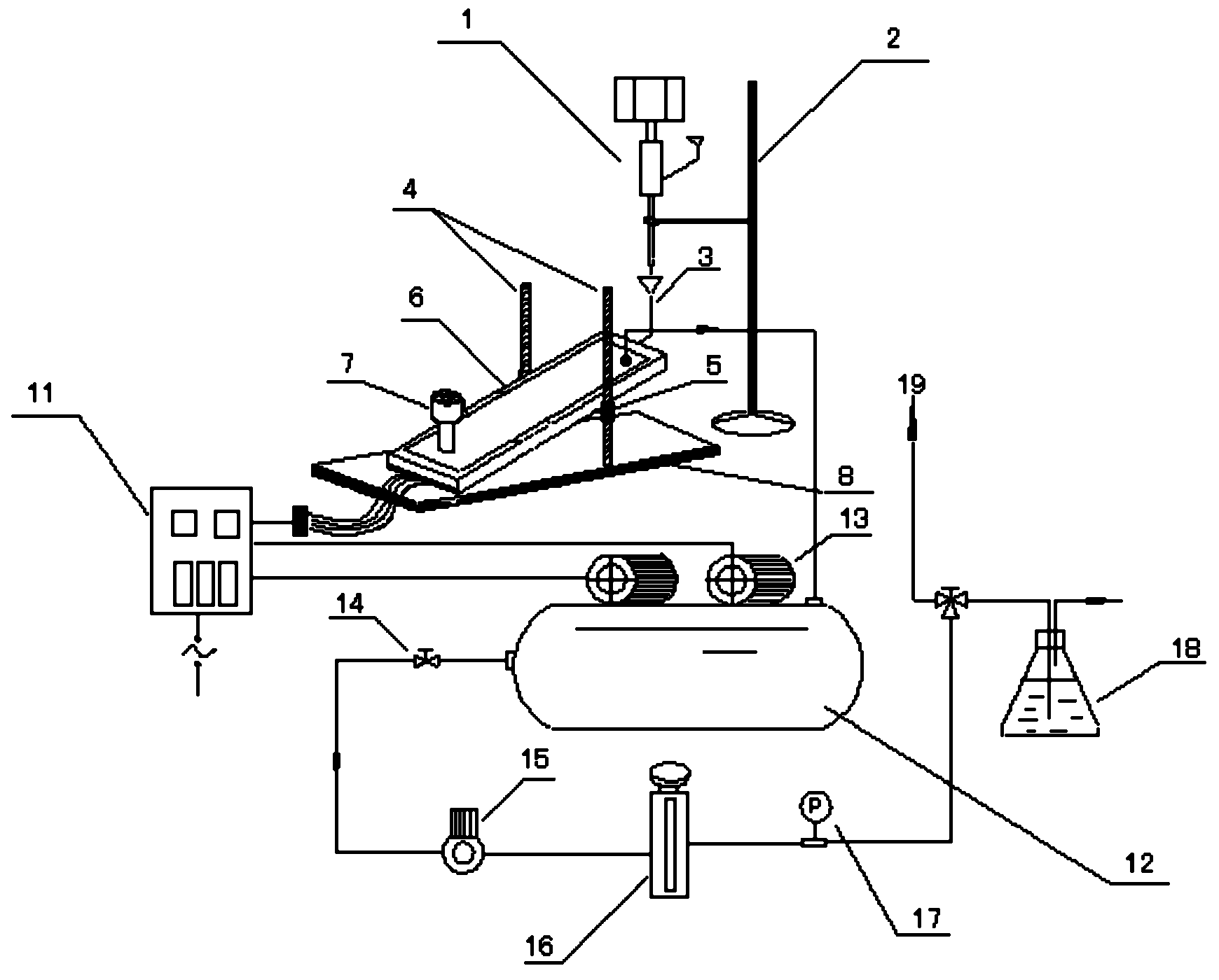
[0018] to combine Figure 1~4 , the present invention includes a liquid methyl iodide vaporization pressurized distribution system, which is mainly composed of a small flow liquid supply device 1, a support 2, a liquid vaporization chamber 6, a filter 7, a base 8 and a distribution system for realizing dynamic distribution of gaseous methyl iodide loop composition.

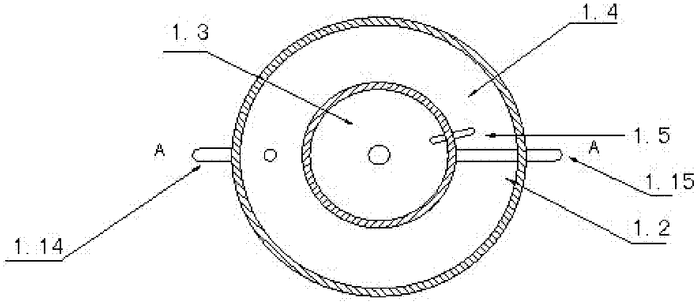
[0019] The above-mentioned small flow liquid supply device 1 is composed of a gas-liquid mixing chamber 1.6, a solution supply chamber 1.3, a solution supply chamber 1.4, a siphon tube 1.5, an upper guide tube 1.8 and a lower guide tube 1.9, the purpose of which is to ensure the flow of liquid under small flow conditions. The long-term stable supply of is obtained by the Bernoulli equation and the continuity equation: In the formula, G is the mass flow rate at the outlet of the device, and A 2 is ...


PUM


Abstract

The invention aims to provide a dynamic distribution system of gaseous methyl iodine. The dynamic distribution system comprises a small-flow liquid supply device, a liquid vaporization chamber and an air compressor, wherein the small-flow liquid supply device is fixed on a bracket; an outlet of the small-flow liquid supply device is arranged in alignment with an inlet of the liquid vaporization chamber; the liquid vaporization chamber is arranged on a pedestal through a threaded supporting rod and a lifting threaded bushing which is matched with the threaded supporting rod; the angle of the liquid vaporization chamber can be adjusted through the lifting threaded bushing; an air suction port is formed below the liquid vaporization chamber; a hole which is connected with the air compressor is formed above the liquid vaporization chamber; an electric heating device is also arranged in the liquid vaporization chamber; and the air compressor is communicated with a gas application environment. According to the dynamic distribution system, long-time continuous stable supply of the small-flow methyl iodine liquid can be realized, and stable concentration of the methyl iodine at the outlet of the system is guaranteed. The suction effect of the air compressor enables that the liquid vaporization chamber is in a negative pressure state all the time; safety and reliability are guaranteed; and no injury is caused to the environment and the operation personnel. The system has the advantages of simple structure, reliable performance and easiness for implementation.

Description

technical field [0001] The invention relates to the fields of chemical industry, environment and medicine, in particular to a device for vaporizing and distributing low-boiling liquid. Background technique [0002] As a clean and efficient energy source, nuclear power is increasingly favored by people. However, the radioactive hazards caused by nuclear power accidents are always worrying. The containment of nuclear power plants is the last barrier to prevent the release of radioactive products to the environment. In the event of a serious accident, due to the continuous increase of non-condensable gases produced by the reaction between the molten core and the concrete floor, the pressure in the containment will gradually increase, and eventually may The integrity of the containment vessel will be destroyed due to overpressure, resulting in the leakage of radioactive substances. The containment filtration and discharge system adopts an active pressure relief method to releas...

Claims


Application Information

Patent Timeline
Patent Type & Authority Applications(China)
IPC IPC(8): G21C15/18G21C15/24
CPCY02E30/40Y02E30/30
Inventor 谷海峰孙中宁周艳民阎昌琪孙立成曹夏昕王建军范广铭
Owner CHINA NUCLEAR POWER ENG CO LTD
Why Eureka
Try Eureka