
WIFI (wireless fidelity) mobile terminal plane antenna

A planar antenna and mobile terminal technology, which is applied to antennas, devices that make antennas work in different frequency bands at the same time, and the structure of radiating elements.

Inactive Publication Date: 2012-08-08
GUANGXI UNIVERSITY OF TECHNOLOGY
View PDF2 Cites 22 Cited by
  • Summary
  • Abstract
  • Description
  • Claims
  • Application Information

AI Technical Summary

Problems solved by technology

In order to improve the receiving sensitivity of mobile terminals and increase the receiving distance, it must be at the expense of improving the performance of the front-end circuit of the system and increasing the system cost. Therefore, it has not been popularized and applied.

Method used


Image

  • WIFI (wireless fidelity) mobile terminal plane antenna
  • WIFI (wireless fidelity) mobile terminal plane antenna
  • WIFI (wireless fidelity) mobile terminal plane antenna

Examples


Embodiment Construction

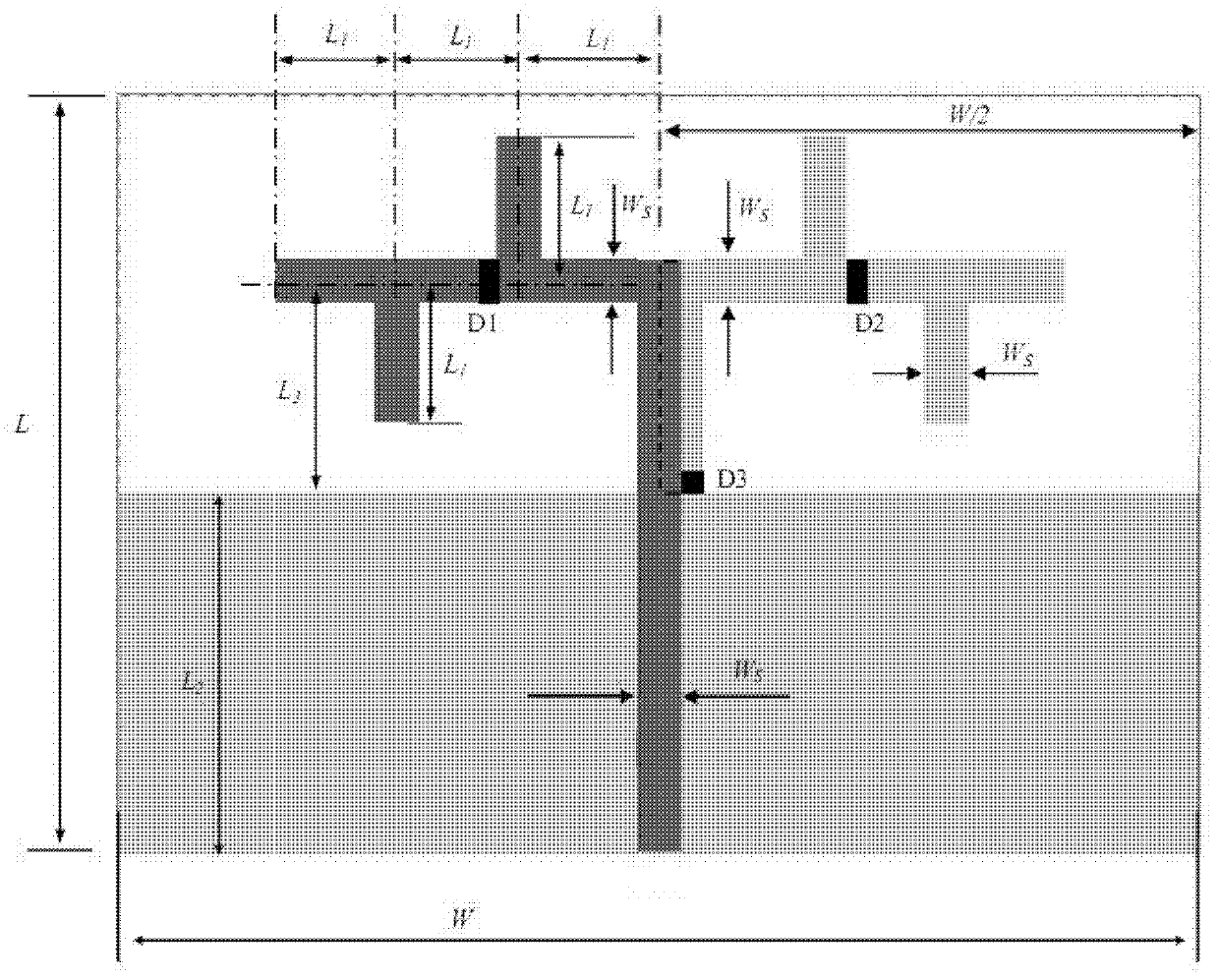
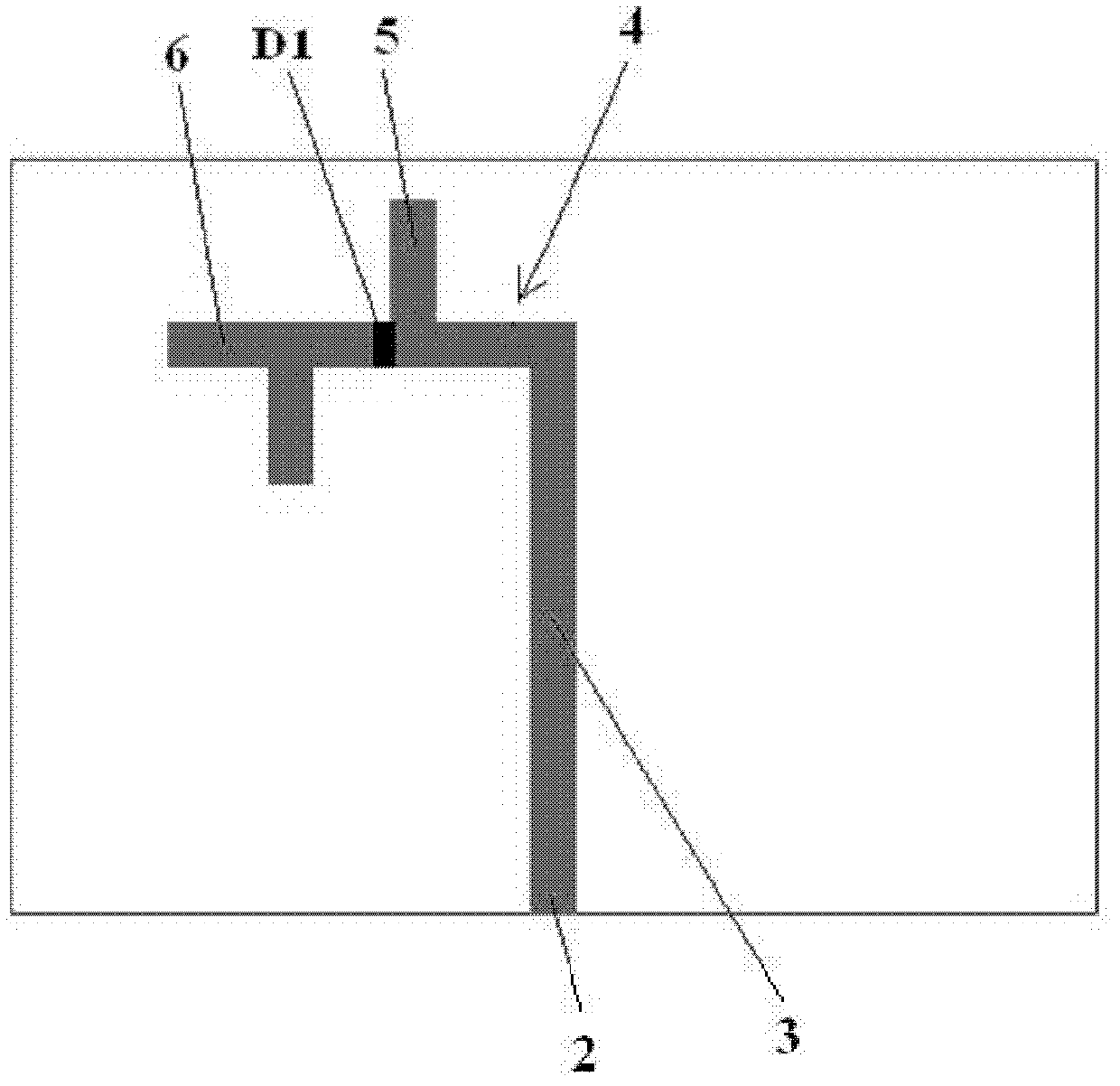
[0031] Such as Figure 1 to Figure 5 As shown, the WIFI mobile terminal planar antenna of the present invention (hereinafter referred to as "planar antenna") includes a dielectric substrate 1, and the planar antenna is formed by corroding corresponding metal patterns on both sides of the double-sided copper-clad dielectric substrate 1. The dielectric substrate 1 is Rectangular structure, the dielectric substrate 1 is an ordinary double-sided copper-clad FR4 printed circuit board, and the relative dielectric constant of the dielectric substrate 1 is ε r , the thickness is h, and the loss tangent is tanσ. The first surface of the dielectric substrate 1 is provided with a microstrip line I3 and a second order tree fractal radiation arm I4 connected to the inner end of the microstrip line I3. On the second surface of the dielectric substrate 1 opposite to the first surface, a ground plate 7, a microstrip line II8 connected to the inner side of the ground plate 7 near the middle, ...


PUM


Abstract

The invention discloses a WIFI (wireless fidelity) mobile terminal plane antenna and relates to a plane antenna. The antenna comprises a medium substrate. One side of the medium substrate is provided with a microstrip line I and a second order tree fractal radiation arm I. The other side of the medium substrate is provided with a ground plate, a microstrip line II and a second order tree fractal radiation arm II. The radiation arms I II form a second order tree fractal dipole radiator. A characteristic impedance of the microstrip lines I II is 50 ohms. A microwave diode I is connected in series to a front end or a rear end of a first branch joint of the radiation arm I. A microwave diode II is connected in series to the front end or the rear end of the first branch joint of the radiation arm II. A microwave diode III is connected in series to the joint of the microstrip line II and the ground plate. The structure of the antenna is changed through controlling on-off states of the three microwave diodes so that the antenna can work in 2.45 and 5.8 GHz frequency ranges. And a radiation pattern of the antenna is changed so that the antenna possesses omnidirectional and directional radiation performance. A volume is small, a structure is simple, cost is low and the performance is good.

Description

technical field [0001] The invention relates to a planar antenna. Background technique [0002] Wireless local area network (Wireless Local Area Networks, WLAN) is a system that uses radio frequency (Radio Frequency, RF) technology for data transmission, which enables various network devices to quickly access the Internet (INTERNET) in a wireless manner. Currently, WLAN protocol standards mainly include the 802.11b and 802.11g standards operating at 2.4GHz and the 802.11a standard operating at 5.8GHz. WIFI (Wireless Fidelity, Wireless Fidelity) technology is a brand of wireless network communication technology based on IEEE802.11 series standards, the purpose is to improve the interoperability between wireless network products based on IEEE802.11 standards (Wi-Fi Alliance), simply put, WIFI is a currently popular wireless networking technology, mostly used to connect mobile terminals (such as laptops, PDAs, mobile phones, tablet computers, etc.) to each other wirelessly. L...

Claims


Application Information

Patent Timeline
IPC IPC(8): H01Q3/22H01Q5/00H01Q1/38H01Q5/20H01Q5/321H01Q5/328
Inventor 曾文波赵嘉
Owner GUANGXI UNIVERSITY OF TECHNOLOGY
Learn More