Closed-loop control LED (Light Emitting Diode) constant-current driving circuit

A technology of constant current drive and drive circuit, applied in electric lamp circuit arrangement, electric light source, lighting device, etc., can solve the problems of poor line regulation rate and load regulation rate, unstable working frequency, poor constant current effect, etc. Simple compensation, convenient application, and simple circuit implementation

Inactive Publication Date: 2012-08-08
QX MICRO DEVICES
View PDF3 Cites 10 Cited by
  • Summary
  • Abstract
  • Description
  • Claims
  • Application Information

AI Technical Summary

Problems solved by technology

The advantage of this method is that the control circuit is simple and the response speed is fast. The disadvantage is that the operating frequency is not fixed, and the frequency is related to the inductance, input voltage, output voltage, hysteresis window, etc.
Other control methods, such as fixed off time, critical continuous mode, etc., also have the disadvantage of not fixed operat

Method used


Image

  • Closed-loop control LED (Light Emitting Diode) constant-current driving circuit
  • Closed-loop control LED (Light Emitting Diode) constant-current driving circuit
  • Closed-loop control LED (Light Emitting Diode) constant-current driving circuit

Examples


no. 1 example

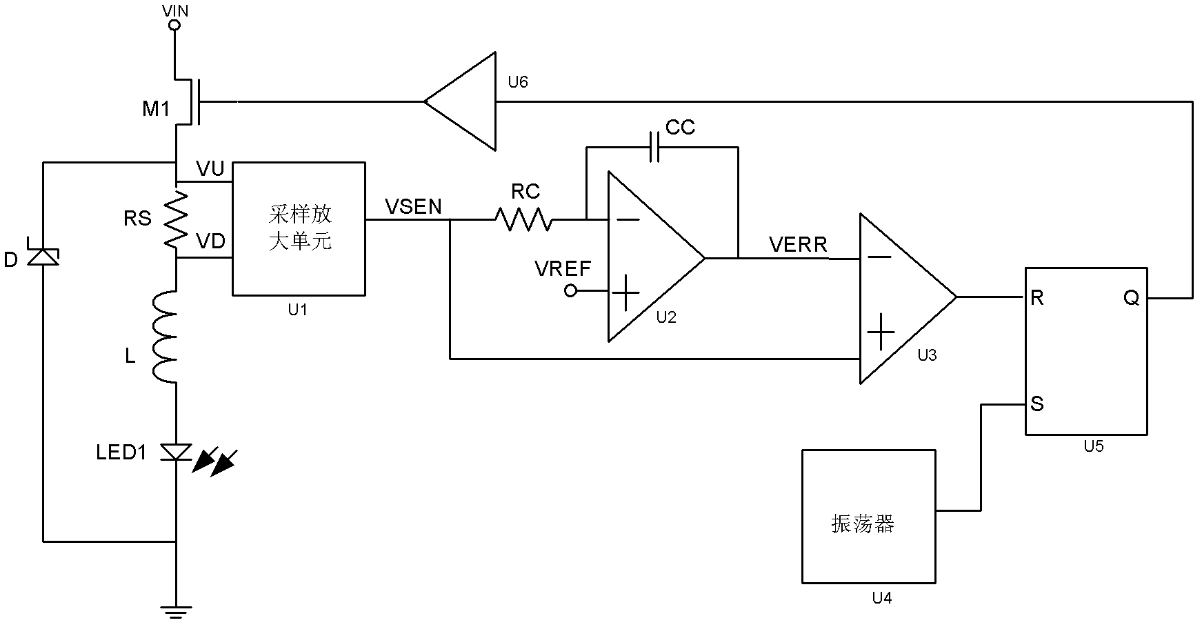
[0040] Such as image 3 As shown, the first embodiment of the LED constant current drive circuit with a fixed operating frequency proposed by the present invention includes a sampling amplifying unit U1, an error amplifier U2, a comparator U3, an oscillator U4, RS flip-flop U5 and power switch drive circuit U6. The output terminal of the power switch driving circuit U6 is electrically connected to the control terminal of the power switch M1. This embodiment also includes a frequency compensation unit composed of an inductor L, a freewheeling diode D, a compensation resistor RC and a compensation capacitor CC.

[0041] The typical operating waveform of the first embodiment is as Figure 4 Shown. Its working principle is: the sampling and amplifying unit U1 samples and amplifies the current information on the inductor L, and converts it into a voltage VSEN proportional to the inductor current. VSEN is compared with the reference voltage VREF, and the error amplifier outputs a vol...

no. 2 example

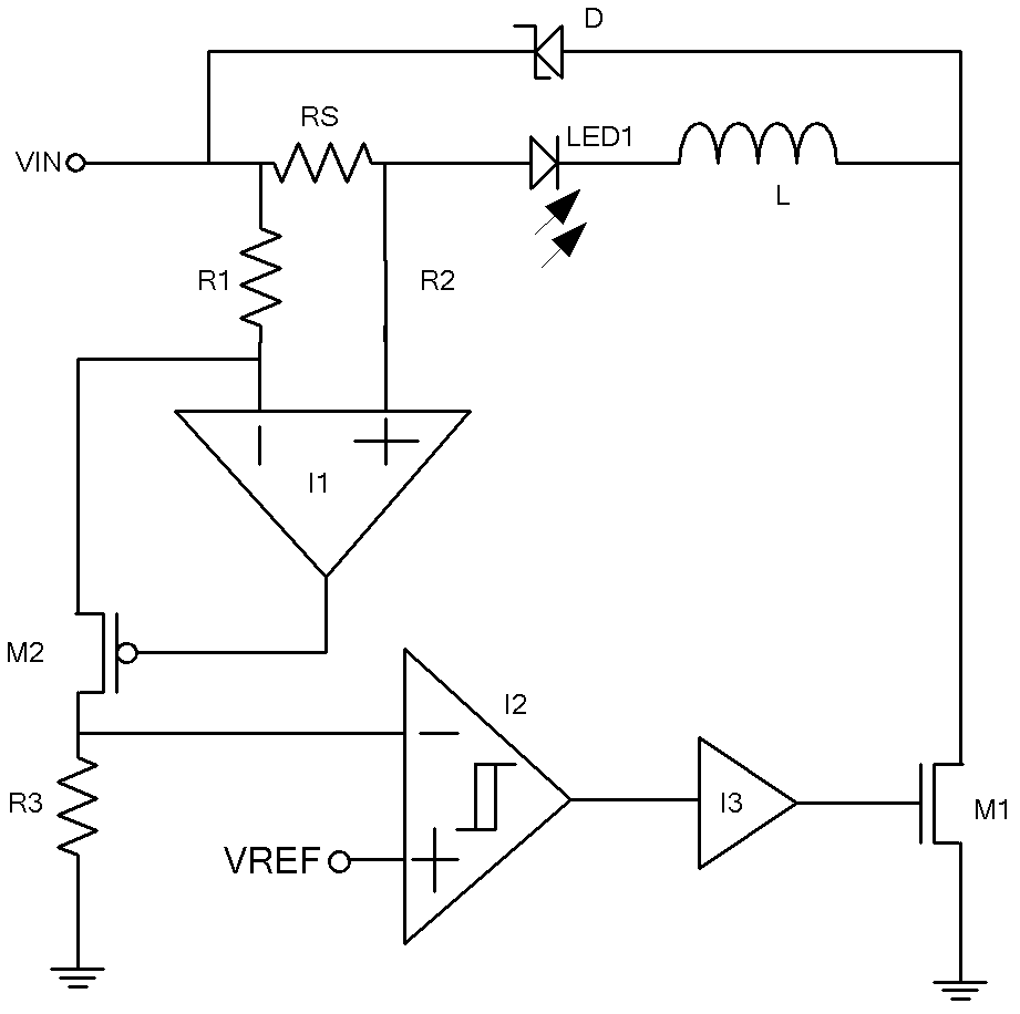
[0049] Such as Image 6 As shown, the second embodiment of the LED constant current drive circuit with a fixed operating frequency proposed by the present invention includes a sampling amplifying unit U1, an error amplifier U2, a comparator U3, an oscillator U4, RS flip-flop U5 and power switch drive circuit U6. The output terminal of the power switch driving circuit U6 is electrically connected to the control terminal of the power switch M1. This embodiment also includes a frequency compensation unit composed of an inductor L, a freewheeling diode D, a compensation resistor RC and a compensation capacitor CC. The difference from the first embodiment is that the power switch M1 is not located at the input power terminal VIN, but at the ground terminal.

[0050] Image 6 Implementation example of medium sampling amplification unit U1 Figure 7 Shown. Correct Figure 5 The simplification removes the current mirror circuit and only includes the operational amplifier I41.


PUM


Abstract

The invention relates to a closed-loop control LED (Light Emitting Diode) constant-current driving circuit, which comprises an inductor (L), a sampling resistor (RS) and a power switch (M1), wherein the inductor (L) and the sampling resistor (RS) are connected with an external LED light source (LED1) in series; and the power switch (M1) is used for disconnecting/conducting a power channel of the external LED light source (LED1). The closed-loop control LED constant-current driving circuit is characterized by further comprising a sampling and amplifying unit (U1), an error amplifier (U2), a comparator (U3), an oscillator (U4), a latching and triggering unit and a power switch driving unit (U6) electrically connected with two ends of the sampling resistor (RS) in sequence; the closed-loop control LED constant-current driving circuit further comprises a frequency compensation unit for ensuring steady loop; and the output end of the power switch driving unit (U6) is electrically connected with the control end of the power switch (M1). The closed-loop control LED constant-current driving circuit disclosed by the invention has fixed switch frequency and good constant-current effect.

Description

Technical field [0001] The invention relates to integrated circuit switch control technology, in particular to a closed-loop control light emitting diode (LED) constant current drive circuit. Background technique [0002] LED lamps have the characteristics of low energy consumption, high luminous efficiency, and long service life, so LED lighting is more and more widely used in lighting and backlighting. However, LEDs usually require constant current drive. At present, one of the common LED constant current driving methods is hysteresis control. The traditional hysteresis control LED constant current driving circuit structure is as figure 1 Shown. The advantage of this method is that the control circuit is simple and the response speed is fast. The disadvantage is that the operating frequency is not fixed, and the frequency is related to the inductance, input voltage, output voltage, and hysteresis window. Other control methods, such as fixed off time, critical continuous mode,...

Claims


Application Information

Patent Timeline
IPC IPC(8): H05B37/02
Inventor 李永红李剑黄朝刚
Owner QX MICRO DEVICES
Why Eureka
Try Eureka