Deconvolution method for extracting evoked potential at high stimulation ratio

A technology of evoked potential and deconvolution, applied in the field of biomedical signal processing, can solve the problems of limiting the clinical research and application of high stimulation rate technology, and achieve the effect of improving reconstruction effect, reducing errors and ensuring original characteristics

Inactive Publication Date: 2012-08-15
SOUTHERN MEDICAL UNIVERSITY
View PDF4 Cites 5 Cited by
  • Summary
  • Abstract
  • Description
  • Claims
  • Application Information

AI Technical Summary

Problems solved by technology
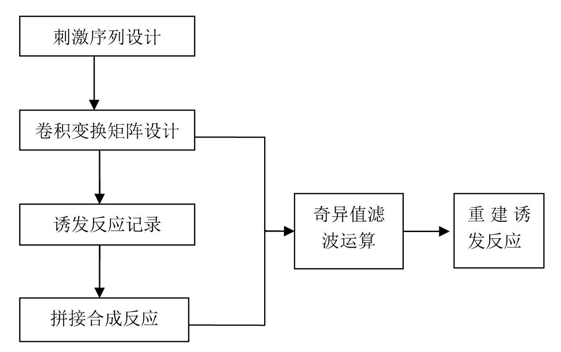
At present, the conventional evoked EEG equipment can only provide stimulation sequences with equal intervals and fixed recording methods, which limits the clinical research and application of high stimulation rate technology.

Method used


Image

  • Deconvolution method for extracting evoked potential at high stimulation ratio
  • Deconvolution method for extracting evoked potential at high stimulation ratio
  • Deconvolution method for extracting evoked potential at high stimulation ratio

Examples


Embodiment 1

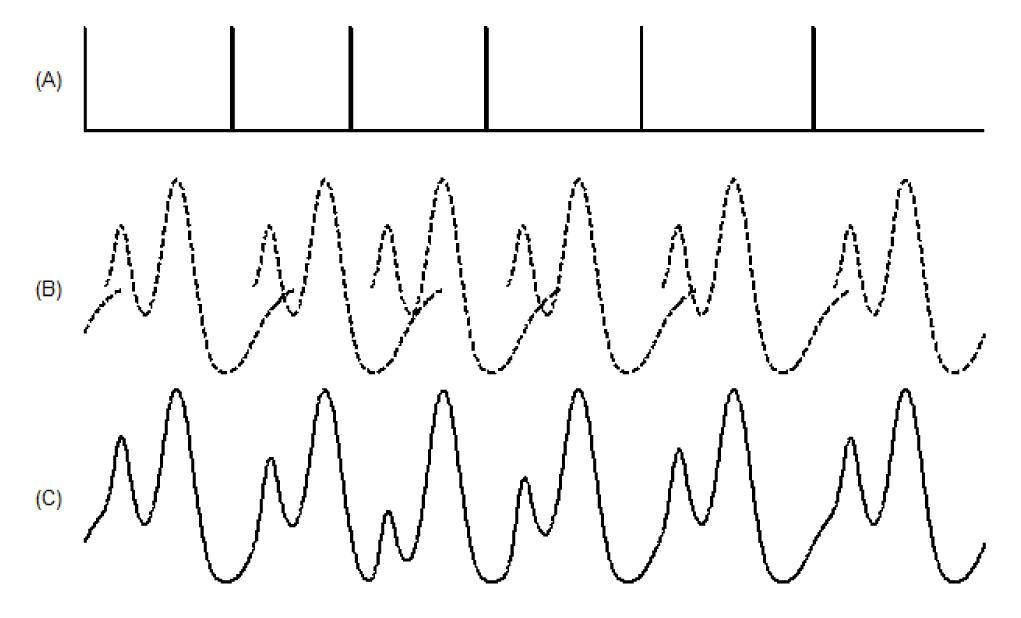
[0063] Example 1: Reconstruction of simulated EP at high stimulation rate

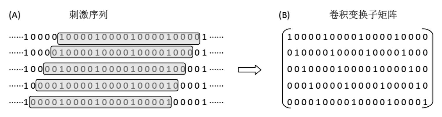
[0064] In the simulation experiment, 7 different stimulation intervals are used: {16.0, 19.0, 22.0, 25.0, 27.8, 30.8, 33.8, 36.8} ms, and the corresponding stimulation rates are: {62.5, 52.6, 45.4, 40.1, 36.0, 32.5, 29.6 , 27.2} S / s; the EP signal to be recovered consists of three waves with different polarities, see image 3 The dotted line in (B). The responses of one stimulation cycle recorded in each round of experiment are spliced ​​according to the order of stimulation rate to form the observation signal as follows: image 3 (A), where the dotted line represents the observed signal formed by splicing the ideal EP signal, and the solid line represents the observed signal formed by splicing the ideal EP signal after adding a certain degree of random noise. The length of the row of the convolution transformation matrix corresponds to a time of 100ms, so the EP signals will overlap under the seven s...

Embodiment 2

[0066] Example 2: Reconstitution of the AMLR at high stimulation rates

[0067] Use the same equipment as in the previous example. Seven stimulation sequences with stimulation rates of 52.6S / s, 47.6S / s, 43.5S / s, 40S / s, 37S / s, 34.5S / s and 32.3S / s were selected, and the interval between stimulations was constant, respectively 19ms, 21ms, 23ms, 25ms, 27ms, 29ms, and 31ms. The total playing time of each stimulus sequence is the same, about 204.8s, and the number of stimuli contained in the 7 stimulus sequences are 10772, 9748, 8909, 8192, 7578, 7066 and 6615 respectively.

[0068] In the normal test group, the subjects were required to have no hearing and neurological medical history, lie quietly on the examination bed, relax the muscles of the whole body, close the eyes, and stay awake during the test.


PUM

PropertyMeasurementUnit
Resistanceaaaaaaaaaa

Abstract

The invention discloses a deconvolution method for extracting an evoked potential at a high stimulation ratio. The deconvolution method comprises the following steps of: acquiring EP (Evoked Potential) waveform signals of a plurality of stimulation periods by adopting an equal-interval stimulation shake-free stimulation sequence according to a stacking average calculation method; generating a convolution conversion sub matrix according to a stimulation sequence parameter of each stimulation period, and further obtaining convolution conversion matrixes of N periods; splicing the average EP signals corresponding to the stimulation periods into a synthesized reaction based on corresponding stimulation ratios; and finally, calculating a transient reaction according to a singular value filter method, and estimating the transient EP according to the transient reaction. The method utilizes same experimental record mode and equipment as the conventional method, special requirements on hardware are eliminated, and an operator is not required to be trained; a singular value filter processing technology is introduced into an EP recovery stage, so that the problem that interference introduced by directly adopting an inverse filter process is enlarged is solved; and the reconstruction effect of the transient EP is improved obviously.

Description

technical field [0001] The invention belongs to the field of biomedical signal processing, and relates to recovering a transient response from overlapping evoked responses at a high stimulation rate during evoked potential recording. Background technique [0002] The neural electrical activity generated by the nervous system under external stimuli is a transient time-domain waveform recorded by related equipment through electrodes, called Evoked Potential (EP). Evoked potentials are of great importance in several disciplines including clinical medicine, electrophysiology, psychology, and cognitive science. At present, evoked potentials are mainly divided into three modes according to different stimulation methods: Auditory Evoked Potential (AEP), Visual Evoked Potential (VEP) and Somatosensory Evoked Potential (SEP). In addition, methods of obtaining evoked responses using other stimuli such as magnetism and laser are also being developed. [0003] When using conventional ...

Claims


Application Information

Patent Timeline
IPC IPC(8): A61B5/04
Inventor 王涛彭贤颜刚林霖
Owner SOUTHERN MEDICAL UNIVERSITY
Why Eureka
Try Eureka