Cement slurry pumping device

A technology of cement mortar and mud pump, which is applied to the device and coating of the surface coating liquid, which can solve the problems of high labor intensity, unsightly site environment, and low work efficiency, so as to reduce labor intensity and avoid site dirty Chaos, the effect of improving work efficiency

Inactive Publication Date: 2012-08-15
XINXING DUCTILE IRON PIPES CO LTD
View PDF5 Cites 0 Cited by
  • Summary
  • Abstract
  • Description
  • Claims
  • Application Information

AI Technical Summary

Problems solved by technology

The main defects of this sedimentation tank mortar cleaning method are: manual excavation is required, labor intensity is high, work efficiency is low, and the site environment is not beautiful

Method used


Image

  • Cement slurry pumping device
  • Cement slurry pumping device
  • Cement slurry pumping device

Examples


Embodiment Construction

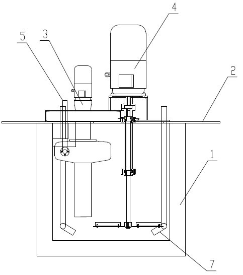
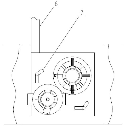
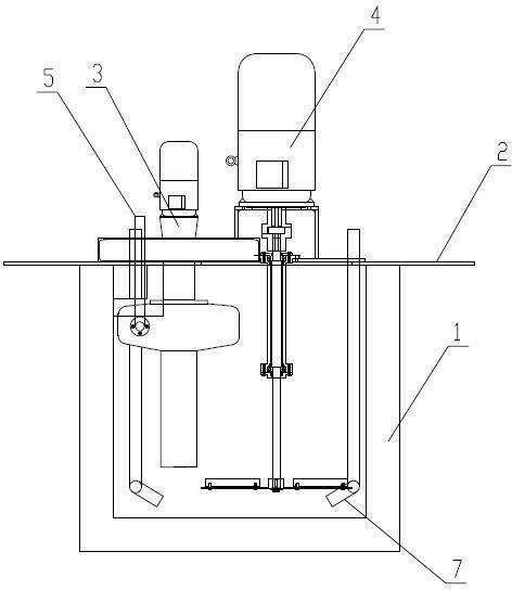
[0015] Such as figure 1 , figure 2 As can be seen from the shown embodiment, the cement mortar pumping device of the present invention includes a settling tank 1, a mud pump 3, an agitator 4, a power agitation device 7 and a PLC controller, and one side of the settling tank 1 is provided with The mortar inlet tank 6, the mud pump 3 is provided with a mortar outlet pipe 5; the input ends of the mud pump 3, the agitator 4 and the power agitation device 7 are respectively connected with the PLC controller through the motor, and the output ends pass through the The cover plate 2 of the sedimentation tank 1 extends into the slurry inside of the sedimentation tank 1 .

[0016] The power agitating device 7 includes a wind source, a ventilation pipe and a spray head, the input end of the ventilation pipe is connected to the wind source, and the output end is connected to the spray head.

[0017] One end of the mud pump outlet pipe 5 is connected with the output end of the mud pump ...


PUM


Abstract

The invention discloses a cement slurry pumping device, belonging to the technical field of coating and lining cement on the inner surface of a nodular cast iron pipe. The cement slurry pumping device comprises a slurry pump, a stirrer and a PLC (Programmable Logic Controller), and the slurry pump is provided with a slurry discharging pipe; and the input ends of the slurry pump and the stirrer are respectively connected with the PLC through a motor, and the output ends of the slurry pump and the stirrer are inserted into the interior of cement slurry. The cement slurry pumping device disclosed by the invention has the advantages that full automatic control of a slurry pumping process is realized by the PLC, the whole process does not need manual participation, the labor strength of workers is largely reduced, and the work efficiency is improved; in addition, cement slurry is directly pumped in a cement slurry storage container outside a workshop so that field mess caused of manual excavation can be avoided and the cleanness of the field environment is protected.

Description

technical field [0001] The invention relates to a cement mortar pumping device, which is suitable for the technical field of lining the inner surface of ductile iron pipes with cement. Background technique [0002] At present, the inner surface of the centrifugal ball milled cast iron pipe at home and abroad needs to be lined with cement, and a certain proportion of mortar is spread on the inner surface of the pipe, and through high-speed rotation, a large centrifugal force is generated, so that the cement adheres to the inner surface of the pipe, and the excess mortar will be released from the pipe. The pipe flows out to the sedimentation tank for sedimentation, and the sedimented water is discharged through the pipe ditch. After the sedimentation tank is full, it needs to be manually excavated and excavated into the ground garbage bucket. The sedimentation tank is cleaned and reused. The main defects of this sedimentation tank mortar cleaning method are: manual excavation ...

Claims


Application Information

Patent Timeline
Patent Type & Authority Applications(China)
IPC IPC(8): B05C11/10B05C7/00
Inventor 张同波闫海峰温海军高明文綦晓平李中生
Owner XINXING DUCTILE IRON PIPES CO LTD
Why Eureka
Try Eureka