Numerical control machine tool for machining wooden handle

A technology for processing machine tools and processing mechanisms, applied in the field of machine tools, can solve the problems of lack of automatic feeding, clamping, and cycle processing devices, backward technology, and high labor intensity of workers, so as to improve automation and production efficiency, reduce labor intensity, The effect of improving product quality

Inactive Publication Date: 2012-08-15
黄山市继林机械制造有限公司
View PDF6 Cites 11 Cited by
  • Summary
  • Abstract
  • Description
  • Claims
  • Application Information

AI Technical Summary

Problems solved by technology

The output and quality of wooden handles are greatly affected by factors such as the technical level of operators and individual differences. In addition, this kind of technology is relatively backward and the labor intensity of workers is high, so it is difficult to realize large-scale and industrialized production.
[0003] Ordinary CNC machine tools are limited by their own structural characteristic

Method used


Image

  • Numerical control machine tool for machining wooden handle
  • Numerical control machine tool for machining wooden handle
  • Numerical control machine tool for machining wooden handle

Examples


Embodiment 1

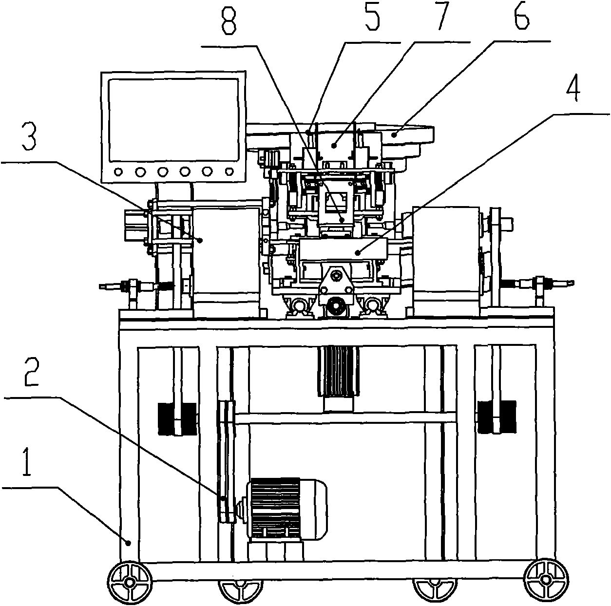
[0036] see figure 1 and figure 2 , a kind of numerical control wooden handle processing machine tool comprises frame 1, motor 2 and numerical control system, and clamping device 3 is installed on described frame 1, is provided with processing mechanism 4 in clamping device 3, and the upper end of processing mechanism 4 is provided with feeding assembly5.

[0037] The feeding assembly 5 includes a vibrating feeding device 6 , a discharging device 7 and a feeding device 8 arranged sequentially from top to bottom.

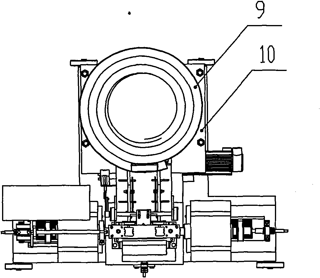
[0038] The vibrating feeding device 6 includes a hopper 9 and a hopper base 10, and the hopper 9 is a spiral structure.

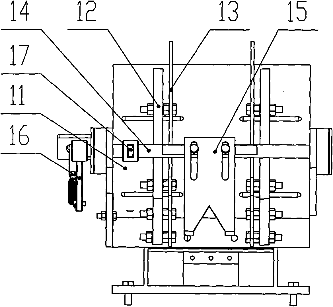
[0039] The discharge device 7 is fixed on the hopper base 10, see image 3 and Figure 4 , the discharge device 7 includes a discharge base 11, a discharge plate 12 is symmetrically fixed on the discharge base 11, and a material limiter 13 is arranged in the discharge plate 12. By adjusting the distance of the material limiter 13, it can be pr...

Embodiment 2

[0049] First, according to the shape of the wooden handle or the requirements of the drawing, the AC3F graphic programming numerical control system is used to complete the programming of the machining program, and to set the position of the turning tool and forming knife and install the chip removal device. After all preparations are completed, the round bar blank is loaded into the vibrating In the hopper 9 of the feeding device 6 and turn on the power, the vibrating feeding device 6 works, when the round bar blanks are arranged up and down in the discharge device 7 along the slideway of the hopper 9, the processing program is started, the material limiting mechanism works, and the number of pieces is limited. 15 is opened, and after sending a round bar blank, the number-limiting piece 15 is closed (every time a processing cycle is completed, the number-limiting piece is opened once). In the groove, at this time, the center of the round bar blank coincides with the centers of ...


PUM


Abstract

The invention discloses a numerical control machine tool for machining a wooden handle, which comprises a frame, a motor and a numerical control system. A clamping device is mounted on a frame, a machining mechanism is arranged in the clamping device, a feeding assembly is arranged at the upper end of the machining mechanism and comprises a vibratory conveying device, a discharging device and a feeding device which are sequentially arranged from top to bottom, the machining mechanism comprises an X-axis feeding device, a Z-axis feeding device, a turning tool rest and a forming tool rest, and chip removal devices are arranged on the turning tool rest and the forming tool rest. By the aid of the numerical control machine tool, conveying, feeding, clamping, machining, discharging, circulatory machining and waste collecting procedures are integrated, automation degree and production efficiency are improved, the labor intensity of workers is relieved, production is increased while consumption is reduced, and product quality is improved.

Description

technical field [0001] The invention belongs to the technical field of machine tools, in particular to a numerically controlled machine tool for processing wooden handles. Background technique [0002] At present, the traditional processing of wooden handles is done manually on special machine tools such as blank clamping, rough turning blanks, finish turning forming, shutdown and unloading. The output and quality of wooden handles are greatly affected by factors such as the technical level of operators and individual differences. In addition, this kind of technology is relatively backward and the labor intensity of workers is high, so it is difficult to realize large-scale and industrialized production. [0003] Ordinary CNC machine tools are limited by their own structural characteristics. Although they can meet the requirements of individual automatic processing during the production process of wooden handles, they cannot collect and process a large amount of wood chips a...

Claims


Application Information

Patent Timeline
IPC IPC(8): B27C7/00B27C7/04B27M3/16
Inventor 高继林
Owner 黄山市继林机械制造有限公司
Why Eureka
Try Eureka