Biomass briquetting machine

A biomass molding machine and machine base technology, which is applied to material molding presses, presses, manufacturing tools, etc., can solve the problems of mold wear, increase power consumption, affect assembly progress, etc., and reduce mold wear. , the effect of reducing safety accidents and enhancing adaptability

Inactive Publication Date: 2012-08-15
CHENGDU WANGAN IND
View PDF11 Cites 10 Cited by
  • Summary
  • Abstract
  • Description
  • Claims
  • Application Information

AI Technical Summary

Problems solved by technology

[0006] First of all, the joint surface between the fixed roller shaft and the roller sleeve is an overflow connection, and the roller sleeve must be heated for a long time before assembly, so that the inner hole of the sleeve can obtain enough expansion, so that it can be smoothly installed on the roller shaft, wasting A large amount of assembly time affects the assembly progress and increases the production cost;
[0007] Second, due to the long heating time and high temperature of the roller sleeve, it inevitably has a certain impact on the material of the roller sleeve, which affects the mechanical properties of the roller sleeve, especially the roller, and shortens the service life of the roller sleeve. ;
[0008] Third, after the roller sleeve is installed on the roller shaft, the contact surface between the roller sleeve and the roller shaft is relatively large, and the heated inner hole expands the roller sleeve due to uneven cooling, and the outer side of the roller sleeve cools quickly, resulting in the middle area of ​​the joint surface is not completely Complete contact, there may even be a gap. When the roller press (mill) is working, the roller sleeve is subjected to high-pressure extrusion. This gap affects the tightness of the roller sleeve and the roller shaft. It reduces the assembly reliability and connection strength of the roller sleeve and the roller shaft, and shortens the service life of the extrusion roller;
[0009] Fourth, the squeeze roller sleeve is a vulnerable part, and the replacement cycle is relatively frequent. The squeeze roller assembled by the hot-fit method needs to be disassembled with special equipment. Generally, the site does not have the ability to disassemble, and it needs to be returned to the factory, which increases maintenance. cost and time;
[0010] Fifth, the roller sleeve is assembled by heating. Due to the high temperature of the roller sleeve, it is convenient to me...

Method used


Image

  • Biomass briquetting machine
  • Biomass briquetting machine
  • Biomass briquetting machine

Examples


Embodiment 1

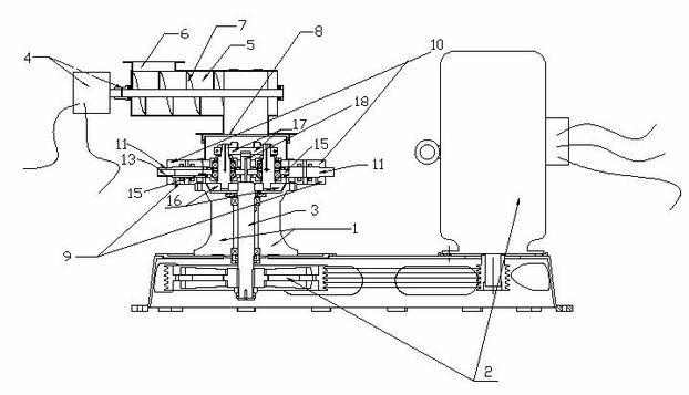
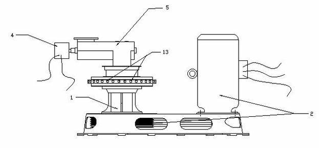
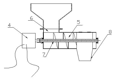
[0086] A biomass forming machine, comprising a machine base 1, a power transmission device 2, a main shaft 3, a feeding device, a pressure roller mechanism and an annular molding die, the feeding device includes a feeding power transmission device 4, a feeding bin 5, Feed inlet 6, discharge port 8 and screw conveyor rod 7, described feeding power transmission device 4 is positioned at the side of feeding bin 5, and feeding inlet 6 is positioned at the top of feeding bin 5 and is close to one end of power transmission device 4, and discharging The port 8 is located at the bottom of the feeding bin 5 and away from the end of the feeding power transmission device 4, the screw conveying rod 7 is located in the feeding bin 5 and connected with the feeding power transmission device 4, the machine base 1 is located below the discharge port 8, and the main shaft 3 is vertically Through the machine base 1, the lower end of the main shaft 3 is connected with the power transmission device...

Embodiment 2

[0088] A biomass forming machine, comprising a machine base 1, a power transmission device 2, a main shaft 3, a feeding device, a pressure roller mechanism and an annular molding die, the feeding device includes a feeding power transmission device 4, a feeding bin 5, Feed inlet 6, discharge port 8 and screw conveyor rod 7, described feeding power transmission device 4 is positioned at the side of feeding bin 5, and feeding inlet 6 is positioned at the top of feeding bin 5 and is close to one end of power transmission device 4, and discharging The port 8 is located at the bottom of the feeding bin 5 and away from the end of the feeding power transmission device 4, the screw conveying rod 7 is located in the feeding bin 5 and connected with the feeding power transmission device 4, the machine base 1 is located below the discharge port 8, and the main shaft 3 is vertically Through the machine base 1, the lower end of the main shaft 3 is connected with the power transmission device...

Embodiment 3

[0090]A biomass forming machine, comprising a machine base 1, a power transmission device 2, a main shaft 3, a feeding device, a pressure roller mechanism and an annular molding die, the feeding device includes a feeding power transmission device 4, a feeding bin 5, Feed inlet 6, discharge port 8 and screw conveyor rod 7, described feeding power transmission device 4 is positioned at the side of feeding bin 5, and feeding inlet 6 is positioned at the top of feeding bin 5 and is close to one end of power transmission device 4, and discharging The port 8 is located at the bottom of the feeding bin 5 and away from the end of the feeding power transmission device 4, the screw conveying rod 7 is located in the feeding bin 5 and connected with the feeding power transmission device 4, the machine base 1 is located below the discharge port 8, and the main shaft 3 is vertically Through the machine base 1, the lower end of the main shaft 3 is connected with the power transmission device ...


PUM


Abstract

The invention discloses a biomass briquetting machine, belonging to the field of processing and molding biomass. The biomass briquetting machine comprises a feeding device, a press roll device, a press roll fixing device, a molding mould and a power transmission device. The biomass briquetting machine has the advantages of saving material, reducing the abrasion for a press roll, being convenient to replace and disassemble, stable and even in feeding and energy-saving, and increasing the yield; and the biomass briquetting machine also has the beneficial effects of being firm in fixation of the press roll and stable in operation of the press roll, and reducing the safety accidents; furthermore, the biomass briquetting machine has the advantages of being simple and convenient in installation and disassembly of the mould, reducing the abrasion for the mould, being smooth in material discharge and high in material adaptability, and reducing the energy consumption.

Description

technical field [0001] The invention discloses a biomass molding machine, which belongs to the field of biomass processing and molding. Background technique [0002] With the introduction of environmental protection theory, burning appliances using biomass as fuel are widely used in industry and life, so biomass processing equipment has emerged as the times require. [0003] First of all, in the feeding process of biomass processing, how to feed and how to make the material uninterrupted, feed evenly and save energy during the feeding process have not been effectively solved. Later, the patent No. 200920311919.7 appeared, the application date was September 29, 2009, and the invention name was a patented technical solution for a biomass feeding device. The patented technical solution is: a biomass feeding device, including a feed port, A feed bin, a screw conveyor, and a feeding port, the bottom of the feed bin is connected to a feed bin, and the feed bin includes a feed bin...

Claims


Application Information

Patent Timeline
IPC IPC(8): B30B11/20B30B15/30B30B15/02B30B15/00
CPCB30B11/207
Inventor 王竹宏
Owner CHENGDU WANGAN IND
Why Eureka
Try Eureka