Method for increasing chlorate decomposition efficiency

A chlorate and efficiency technology, applied in the field of ion-exchange membrane caustic soda preparation, can solve the problems of unqualified caustic soda quality and unstable device operation, and achieve the effects of satisfying brine quality requirements and caustic soda quality requirements, improving decomposition efficiency, and heating uniformly

Active Publication Date: 2012-08-15
SHANDONG DONGYUE FLUO SILICON MATERIALS CO LTD
View PDF3 Cites 11 Cited by
  • Summary
  • Abstract
  • Description
  • Claims
  • Application Information

AI Technical Summary

Problems solved by technology

At present, in the domestic ionic membrane caustic soda industry, there has always been a problem of unstable operation of t

Method used


Image

  • Method for increasing chlorate decomposition efficiency
  • Method for increasing chlorate decomposition efficiency
  • Method for increasing chlorate decomposition efficiency

Examples


Embodiment 1

[0027] The mass ratio of the light brine used to decompose chlorate to the light brine coming out of the electrolytic cell is 1:1.6, the peracidity of light brine after decomposing chlorate is 32g / l, and the chlorate content of imported light brine is 40g / l. The chlorate content at the outlet is 3.5g / l, the temperature of light brine in the decomposition tank is 97°C, and the decomposition rate is 93.75%.

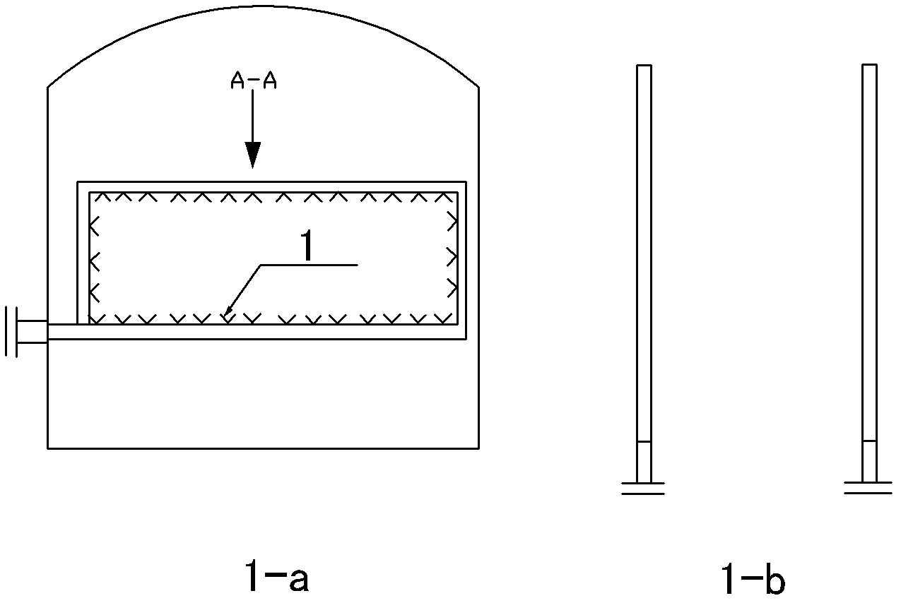
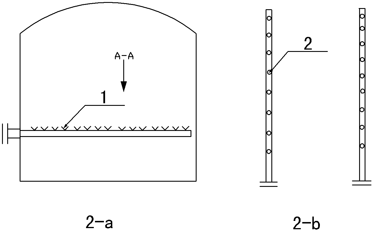
[0028] Such as Figure 1~2 As shown, the steam heating tubes 1 in the chlorate decomposition tank are arranged in double layers, and the lower layer is used to spray gas upwards and the upper layer is to spray gas downwards. Steam nozzles 2 are evenly distributed on the steam heating tubes 1 .

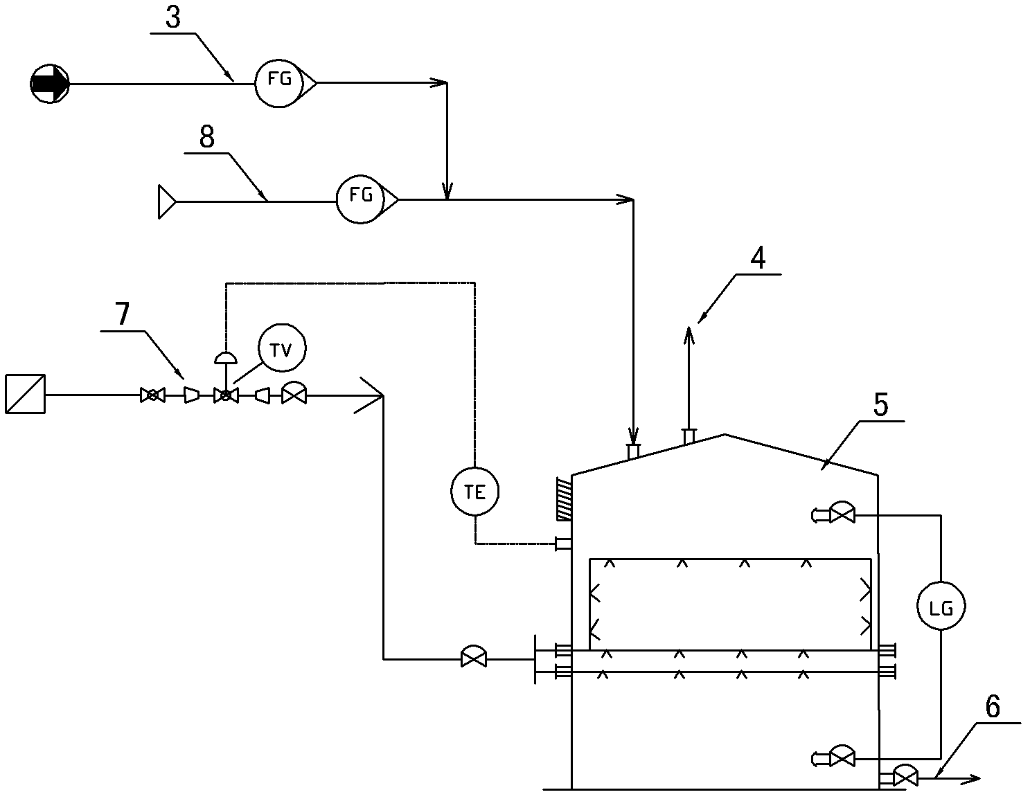
[0029] process such as image 3 Shown:

[0030] The light brine from the light brine inlet 8 of the electrolytic cell is mixed with the 31% hydrochloric acid entering from the hydrochloric acid inlet 3 according to a certain ratio and then enters the chlorate decomposition tank 5....

Embodiment 2

[0032] The mass ratio of the light brine used to decompose chlorate to the light brine coming out of the electrolytic cell is 1:1.4, the peracidity of light brine after decomposing chlorate is 25g / l, and the chlorate content of imported light brine is 12g / l. The outlet chlorate content is 2g / l, the light brine temperature in the decomposition tank is 95°C, and the decomposition rate is 83%.

[0033] The structure and process flow of the steam heating pipe in the chlorate decomposition tank are as in Example 1.

Embodiment 3

[0035] The mass ratio of the light brine used to decompose chlorate to the light brine coming out of the electrolytic cell is 1:1.5, the peracidity of light brine after decomposing chlorate is 30g / l, and the chlorate content of imported light brine is 20g / l. The outlet chlorate content is 2g / l, the light brine temperature in the decomposition tank is 97°C, and the decomposition rate is 90%.

[0036] The structure and process flow of the steam heating pipe in the chlorate decomposition tank are as in Example 1.


PUM


Abstract

The invention relates to a method for increasing chlorate decomposition efficiency, which belongs to the technical field of preparation of ion film caustic soda. The method is realized by means of improving the structures of steam heating tubes in a chlorate decomposition tank and adjusting parameters of a decomposition process. The steam heating tubes are arranged in double layers, the steam heating tubes on the lower layer upwards spray gas, the steam heating tubes on the upper layer downwards spray gas, and steam nozzles are uniformly arranged on the steam heating tubes. The process parameters include that the mass ratio of light salt brine for decomposing chlorate to outflow light salt brine of an electrolyzer is 1:1.4-1.6; preacid of the light salt brine after the light salt brine decomposes the chlorate is controlled in a range from 25g/l to 32g/l; and the temperature of the light salt brine in the chlorate decomposition tank ranges from 94 DEG C to 97 DEG C. Uniformity of the temperature in the chlorate decomposition tank is improved, decomposition stability is ensured, chlorate decomposition rate reaches 82-95%, and the content of the chlorate in the salt brine of a device is ensured to be qualified and stable.

Description

technical field [0001] The invention relates to a method for improving the decomposition efficiency of chlorate, which belongs to the technical field of ion membrane caustic soda preparation. Background technique [0002] In the production equipment of caustic soda produced by ionic membrane, chlorate will be generated due to the side reaction of electrolysis. Excessive chlorate content will not only affect the quality of brine, but also reduce the efficiency of electrolysis. After electrolysis of salt water, most of the 200g / l light brine from the electrolytic cell goes to the dechlorination device to remove free chlorine, and then returns to the primary brine section to recycle salt, and a small part of it goes to the chlorate decomposition equipment to reduce the chlorate content and then go to dechlorination The device removes free chlorine and then returns to the brine section, so decomposing the chlorate in this part of the brine can balance the overall content of the ...

Claims


Application Information

Patent Timeline
IPC IPC(8): C25B1/16
Inventor 魏军海张秀伸
Owner SHANDONG DONGYUE FLUO SILICON MATERIALS CO LTD
Why Eureka
Try Eureka