High-pressure hydraulic injection system

A technology of injection system and high-pressure liquid, applied in shaft equipment, shaft lining, mining equipment, etc., can solve the problems of harsh working environment, large amount of dust and rebound on the working face, laborious construction operation, etc., to reduce construction time and The cost, the spray effect is remarkable, and the effect of making up for the large amount of rebound

Active Publication Date: 2012-08-15
SHANDONG UNIV
View PDF4 Cites 8 Cited by
  • Summary
  • Abstract
  • Description
  • Claims
  • Application Information

AI Technical Summary

Problems solved by technology

However, there are also many inherent defects: ①The amount of dust and rebound of the working flour is large, the working environment is harsh, and there is a pulse phenomenon and poor uniformity when spraying the material; ②The actual water-cement mass ratio is not easy to accurately control, which affects the shotcrete quality; ③ low production efficiency
Similarly, it also has many disadvantages: ①The wet shotcrete construction process is more complicated than the dry shotcrete process, and the materials need to be used together, otherwise they will deteriorate rapidly and cannot be used and will be wasted; ②The adaptability to wet or water-bearing strata is poor; ③For construction in areas that are difficult to enter and exit, due to the large size of the machinery, it is very inconvenient to use, and it lacks flexibility for projects with small usage; ④Complicated and huge mechanical equipment, high maintenance costs, short transportation distance, and laborious construction operations

Method used


Image

  • High-pressure hydraulic injection system
  • High-pressure hydraulic injection system
  • High-pressure hydraulic injection system

Examples


Embodiment Construction

[0026] The present invention will be further described below in conjunction with the accompanying drawings.

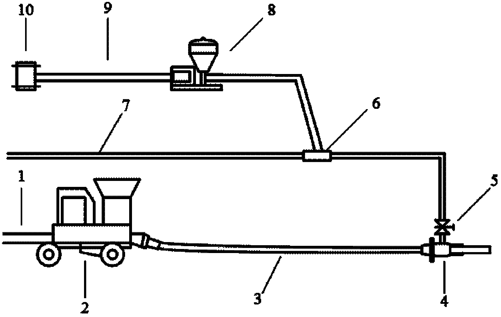
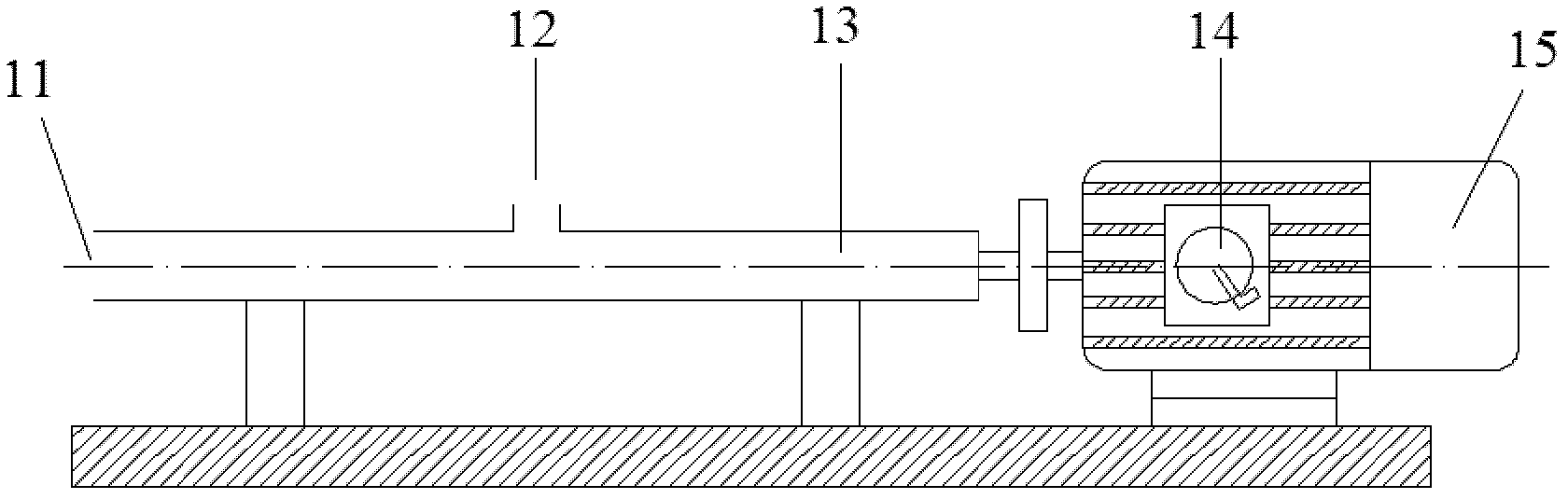
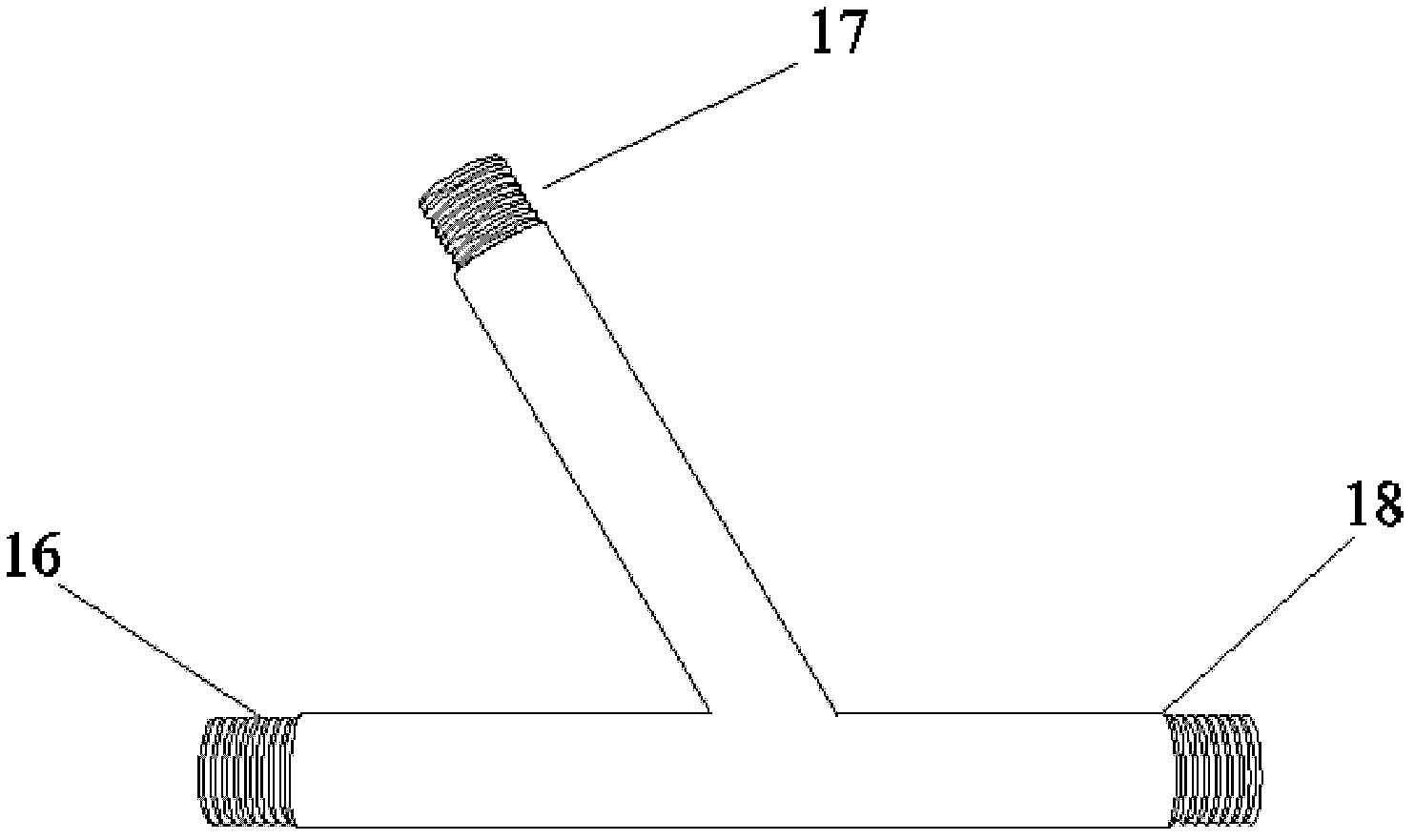
[0027] A high-pressure hydraulic injection system includes a sprayer, an accelerator container, a liquid accelerator supply machine, an accelerator mixing pipe and a nozzle, such as figure 1 As shown, among them, the injection machine is connected with the nozzle through the delivery hose; the accelerator container is connected with the liquid accelerator supply machine through the accelerator delivery pipe; the accelerator mixing pipe is a three-way structure, such as image 3 As shown, the three openings are feed port I, feed port II and discharge port I respectively. The liquid accelerator supply machine is connected to the feed port I of the quick-setting agent mixing pipe through the delivery hose, and the feed port The II is connected with a high-pressure water pipe, and the discharge port I is connected with the nozzle through the high-pressure water pipe.

[0...


PUM


Abstract

The invention discloses a high-pressure hydraulic injection system. The high-pressure hydraulic injection system comprises an injection machine, a setting accelerator container, a liquid setting accelerator feeder, a setting accelerator mixing pipe and a nozzle, wherein the injection machine is connected with the nozzle through a material conveying hose, the setting accelerator container is connected with the liquid setting accelerator feeder through a setting accelerator material conveying pipe, the setting accelerator mixing pipe has a tee structure with three openings, namely a feed port I, a feed port II and a discharge port I, the liquid setting accelerator feeder is connected with the feed port I of the setting accelerator mixing pipe through a material conveying hose, the feed port II is connected with a high-pressure water pipe, and the discharge port I is connected with the nozzle through the high-pressure water pipe. The high-pressure hydraulic injection system has the following advantages: 1. the high-pressure hydraulic injection system enables liquid setting accelerator to be applied, and the liquid setting accelerator can effectively reduce the resilience and dust capacity of concrete in construction, improve the working environment and save cost; and 2. a dry injection technology is changed to wet injection, the equipment is simple and flexible, the construction is simple and convenient, and the operation is easy.

Description

technical field [0001] The invention relates to a concrete spraying system, in particular to a new type of separated wet spraying system—high-pressure hydraulic spraying system. Background technique [0002] The construction process system of shotcrete is composed of three subsystems: material supply, air supply and water supply. Different combinations of these three subsystems produce different construction techniques and construction techniques, which have a significant impact on the quality of shotcrete, and the construction cost is also vary. [0003] At present, there are mainly two methods of preparing sprayed concrete, namely dry-mix spraying and wet-mix spraying. The dry-mix shotcrete is to deliver the dry mix (cement, aggregate and powder quick-setting agent) to the nozzle with the help of a jet machine driven by compressed air, and spray it to the sprayed surface after adding water. The wet-mix shotcrete is to send the wet mix (cement, aggregate and water) to the...

Claims


Application Information

Patent Timeline
Patent Type & Authority Applications(China)
IPC IPC(8): E21D11/10
Inventor 李树忱张露晨李术才冯丙阳袁超徐钦健
Owner SHANDONG UNIV
Why Eureka
Try Eureka