Pneumatic cooling and air purifying system

An air purification system and air purification device technology, applied in the direction of machine/engine, safety device, non-variable-capacity pump, etc., can solve the problems of not being able to store for a long time, large-capacity batteries increase risk factors, etc., to achieve strong adaptability and operation. Safe and reliable effect

Inactive Publication Date: 2012-08-15
中平能化集团机械制造有限公司
View PDF10 Cites 5 Cited by
  • Summary
  • Abstract
  • Description
  • Claims
  • Application Information

AI Technical Summary

Problems solved by technology

[0005] In the above background, there are two main types of cooling and air purification technologies currently available: one is ice making and ice storage, which uses the phase change of ice to absorb heat, and is driven by a large-capacity battery in storage for cooling and air circulation Large-capacity batteries increase the risk factor in a relatively closed safe place; the other is to store liquid carbon dioxide, and use the throttling effect to drive the carbon dioxide used for air circulation after cooling down and reducing pressure. Air motor, but limited by the critical temperature of carbon dioxide, the system cannot be stored in an environment higher than 30°C for a long time

Method used


Image

  • Pneumatic cooling and air purifying system
  • Pneumatic cooling and air purifying system
  • Pneumatic cooling and air purifying system

Examples


Embodiment 1

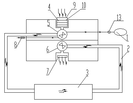
[0025] Depend on figure 1 and figure 2 A pneumatic cooling and air purification system shown includes an air purification device 4 arranged at the air suction port, and a first pneumatic fan 5 connected to the air duct 2 at the air outlet, that is, the inlet of the air duct 2 and the first pneumatic fan 5 The air outlet of the air flow channel 2 is provided with a cooling device, the end of the air flow channel 2 is provided with an outlet, and the outlet of the air flow channel 2 is provided with a second fan 6 for pressurization. Move the freely rotating impeller or be a hand fan with a handle, and the second fan 6 is convenient for sucking cold air from the air flow duct 2 into a safe place to avoid danger. The air outlet of the second fan 6 is provided with shutters 7, and the shutters 7 are used to release cold wind and adjust the angle of cold wind.

[0026] Air cleaning device 4 comprises the cabinet body 9 that the top is provided with gas inlet, and the bottom is ...

Embodiment 2

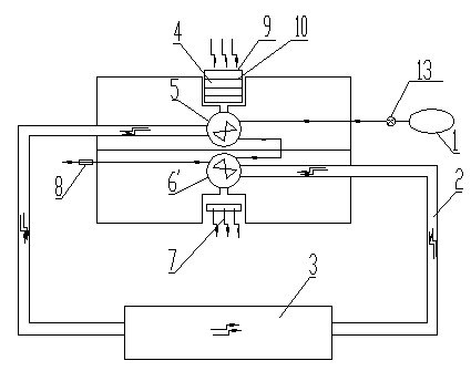
[0031] Depend on image 3 and Figure 4 A kind of pneumatic cooling and air purification system shown is different from Embodiment 1 in that: under the condition that the aforementioned air source is sufficient, the second blower is the second pneumatic blower 6 ′, and the first pneumatic blower 5 The air path of the air motor 5 a and the air motor 6 a of the second air blower 6 ′ is connected in series, and the exhaust port of the air motor 6 a of the second air blower 6 ′ is exhausted through the muffler 8 .

[0032] After replacing the second fan 6 with the second pneumatic fan 6', the compressed gas in the air source or the gas in the mine pressure air pipeline 15 enters the air motor 5a of the first pneumatic fan 5 and drives it to rotate, and the discharged gas enters The air motor 6a of the second air blower 6' drives the second air blower 6' for pressurization. This method can obtain a higher fan speed and is suitable for high-speed and low-torque fans.

Embodiment 3

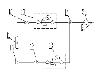
[0034] Depend on Figure 5 and Figure 6 A kind of pneumatic cooling and air purification system shown is different from Embodiment 1 in that: under the condition that the aforementioned air source is sufficient, the second fan is the second pneumatic fan 6', the storage tank 11 and the mine pressure After the air pipeline 15 is respectively connected to a switching valve 14 through an air source processing device 13, the switching valve 14 is connected to a three-way valve 18 through the pipeline, and the three-way valve 18 is connected to the first and second pneumatic valves respectively through the pipeline. The two air motors of blower fan, i.e. the air motor 5a of the first air blower 5 and the air motor 6a of the second air blower 6' are connected with the air source respectively, so that the air motor 5a of the first air blower 5 and the second air blower 6' The air path of the air motor 6a is connected in parallel, and the air motor 5a of the first air blower 5 is co...


PUM


Abstract

The invention discloses a pneumatic cooling and air purifying system comprising an air purifying device arranged at an air suction opening and a first pneumatic blower connected with an air duct at an air outlet, wherein a cooling device is arranged on the air duct, and the air duct is provided with an outlet; and the pneumatic motor of the first pneumatic blower is connected with an air source system, and the air source of the air source system is a storage tank filled with compressed air and/or a mine pressure air pipeline. The pneumatic cooling and air purifying system disclosed by the invention has the advantages of strong adaptability, good safety and reliability and no need of electric drive.

Description

technical field [0001] The invention belongs to the field of mine security and emergency avoidance, and in particular relates to a pneumatic cooling, dehumidification and air purification system. Background technique [0002] When mine accidents or other people's lives are threatened, mine rescue cabins, refuge chambers and security facilities become safe havens for people in distress. [0003] Under normal circumstances, safety shelters such as mine rescue cabins, refuge chambers, and security facilities can provide oxygen, food, and drinking water necessary for personnel to survive, and can also achieve internal temperature and humidity control, remove harmful gases exhaled by the human body, and maintain A suitable environment for the human body. [0004] However, after a disaster such as a mine disaster occurs, safe havens such as mine rescue cabins, refuge chambers and security facilities are very likely to lose any external supply. Therefore, the above-mentioned safe...

Claims


Application Information

Patent Timeline
Patent Type & Authority Applications(China)
IPC IPC(8): E21F11/00E21F3/00F04D25/04
Inventor 渠清团李付生吴连成张国平王振龙王冠鑫付转张利民邵翔宇王汉兴张凤盛光磊
Owner 中平能化集团机械制造有限公司
Why Eureka
Try Eureka