Multiple-effect drying technology

A drying process and drying technology, applied in the direction of drying gas arrangement, drying, drying machine, etc., can solve difficult energy-saving tasks, reduce waste gas energy grade, pollute the environment and other problems

Inactive Publication Date: 2014-04-23
QINGDAO HAILIN ELECTRONICS MATERIALS TECH
View PDF5 Cites 1 Cited by
  • Summary
  • Abstract
  • Description
  • Claims
  • Application Information

AI Technical Summary

Problems solved by technology

Although these schemes have improved the energy utilization rate to a certain extent, the direct mixing of exhaust gas and fresh air greatly reduces the energy grade of exhaust gas, and most of the exhaust gas (temperature is 60-150°C, relative humidity is 60%-90%) ) directly discharged, recovering the heat of this part of high-humidity exhaust gas and making it have a higher energy grade is a very promising and difficult energy-saving task
At the same time, the direct evacuation of these exhaust gases has caused the following effects: first, the discharged high-temperature and humid air causes visual pollution; second, the particulate dust of the exhaust gas is discharged into the atmosphere to pollute the environment; third, the waste heat of the exhaust gas is not recycled and is a serious waste of energy

Method used


Image

  • Multiple-effect drying technology
  • Multiple-effect drying technology

Examples


Embodiment 1

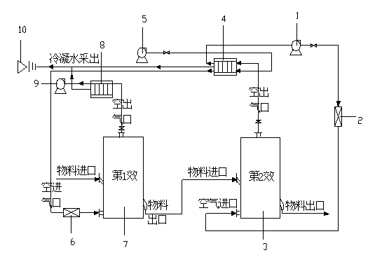
[0031] This embodiment is an example of two-effect drying.

[0032] Such as figure 2 As shown, the two-effect drying system includes a two-stage drying system connected in series. In one operation cycle, the first effect drying chamber 7 is included, the drying medium outlet is connected to the hot air inlet of the heat exchanger 8, the hot air outlet of the heat exchanger 8 is connected to the induced draft fan 9, and the drying medium inlet is connected to the heat exchanger 4 The cold air outlet, the cold air inlet of the heat exchanger 4 is connected to the fan 5, the connecting pipe between the heat exchanger 4 and the first effect drying chamber 7 is provided with an auxiliary heat source 6; the other end of the heat exchanger 4 is connected to the hot air inlet The drying medium outlet of the second effect drying chamber 3, the hot air outlet of the heat exchanger 4 is connected to the drying medium inlet of the second effect drying chamber 3 through the induced draft...

Embodiment 2

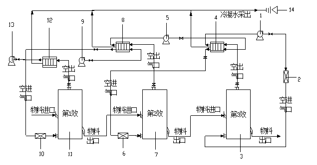
[0037] This embodiment is an example of a three-effect air drying process.

[0038] As shown in Figure 3, the three-effect drying system includes a series of three-stage drying systems. The first effect drying chamber 11 is included in one operation cycle, and its drying medium outlet is connected to the hot air inlet of heat exchanger 12 through induced draft fan 13, and its drying medium inlet is connected to the cold air outlet of heat exchanger 8, and the outlet of heat exchanger 8 The inlet of the cold air is connected to the fan 9, and the connecting pipe between the heat exchanger 8 and the first effect drying chamber 11 is provided with an auxiliary heat source 10; the hot air inlet at the other end of the heat exchanger 8 is connected to the drying medium of the second effect drying chamber 7 Outlet, the hot air outlet of the heat exchanger 8 is connected to the cold air inlet of the heat exchanger 4 through the induced draft fan 5, and the cold air outlet of the heat...


PUM


Abstract

The invention relates to a multiple-effect drying technology which is characterized in that air serves as drying medium and directly contacts with material to be dried to take away moisture and provide heat; multiple stags of drying chambers connected with a heater and a heating device are connected in series to form a simulated moving bed operation mode; air lead out of the last stage is subjected to heat exchange by an air heat exchanger to heat dry medium of the last but one stage; air led out of the last but one stage is subjected to heat exchange by the air heat exchanger to heat the drying medium of the last but two stage; and the rest can be deduced by analogy. The multiple-effect drying technology has the advantages of energy saving and high efficiency, is efficient and quick and is simple to manufacture.

Description

technical field [0001] The invention relates to a drying process, in particular to a multi-effect drying process using a heat exchanger to exchange heat between high-temperature humid air and cold air to recover energy from high-temperature and high-humidity air. Background technique [0002] Drying is one of the most energy-intensive unit operations. According to statistics, the sum of drying energy consumption of various industries in the UK accounts for about 8% of the total energy consumption of the entire industrial system, while the proportion of drying energy consumption in my country to the entire industrial energy consumption is half higher than that in the UK, reaching 12%. At present, the utilization rate of drying energy in general chemical industry production in my country is only 20%-60%. [0003] At present, many scholars have carried out research on the process of multi-stage drying and waste gas recovery, and proposed a multi-stage and multi-stage drying me...

Claims


Application Information

Patent Timeline
Patent Type & Authority Patents(China)
IPC IPC(8): F26B21/00
Inventor 胡城李红张佩张伟涛胡仰栋
Owner QINGDAO HAILIN ELECTRONICS MATERIALS TECH
Why Eureka
Try Eureka