

Cylinder wall residual heat recovery and heat transfer device of dry method cement rotary kiln
A cement rotary kiln and waste heat recovery technology, applied in rotary drum furnace, waste heat treatment, lighting and heating equipment, etc., can solve the problem that the project has not been reported, waste heat recovery sealing, low grade, and the surface waste heat of cement rotary kiln has not been effectively used. Use and other issues to achieve the effect of improving the waste heat recovery rate, increasing the power generation, and promoting the application value.
- Summary
- Abstract
- Description
- Claims
- Application Information
AI Technical Summary
Problems solved by technology
Method used
Image

Examples
Embodiment 1
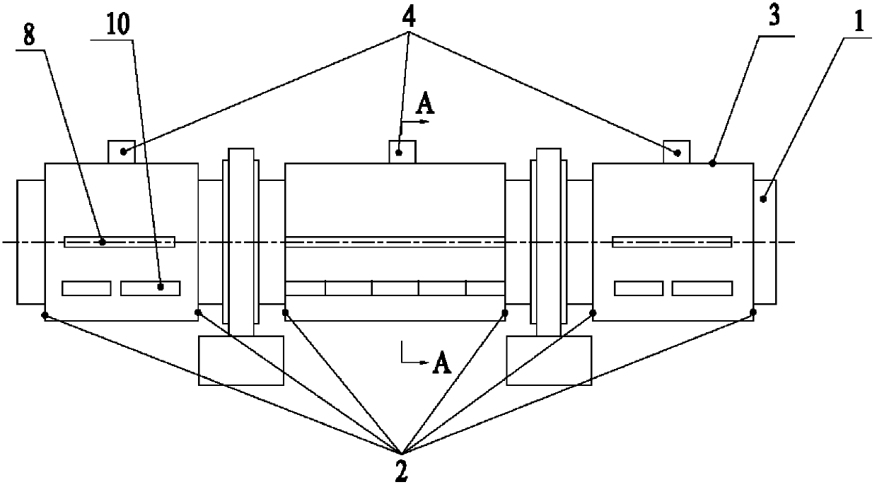
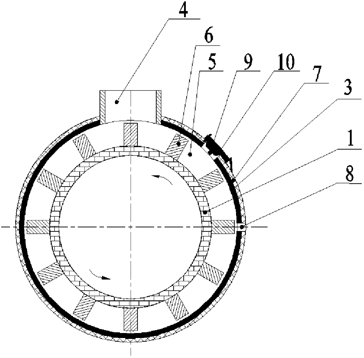
[0025] see figure 1 with image 3 As shown, a dry-process cement rotary kiln wall waste heat recovery heat exchange device includes a cement rotary kiln kiln body 1, and one or more fixed outer cylinder walls 3 are set on the outside of the cement rotary kiln kiln body 1, and the outer cylinder wall 3 There are working fluid inlets 2 at both ends, and there is a gap between the outer surface of the cement rotary kiln body 1 and the inner surface of the outer cylinder wall 3 to form a working medium flow channel and a heat exchange space. exit 4.
[0026] Blades 6 are provided on the surface of the cement rotary kiln body 1. On the one hand, the blades 6 can increase the heat dissipation area and enhance heat exchange. Circumferential flow prolongs the contact and heat exchange time between the heat-exchanging working medium 5 and the cement rotary kiln 1, thereby enhancing the heat-exchanging effect between the heat-exchanging working medium 5 and the surface of the cement r...
Embodiment 2
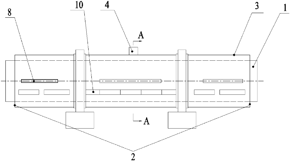
[0033] see figure 2 As shown, it is different from Embodiment 1 in that: a section of fixed outer cylinder wall 3 is set on the outer side of cement rotary kiln kiln body 1, which is an overall arrangement.
PUM
 Abstract
Description
Claims
Application Information