Two-phase hollow-core compensation pulse generator and method for realizing pulse discharge

A technology for compensating pulses and pulse discharges, applied in the direction of controlling generators, electrical components, electromechanical devices, etc., can solve problems such as speed output current pulse width constraints, achieve the effect of miniaturization, increase energy density and power density

Inactive Publication Date: 2014-02-19
HARBIN INST OF TECH
View PDF3 Cites 0 Cited by
  • Summary
  • Abstract
  • Description
  • Claims
  • Application Information

AI Technical Summary

Problems solved by technology

[0004] The purpose of the present invention is to solve the problem that the speed of the existing air-core compensation pulse generator is restricted by the output current pulse width, and propose a two-phase air-core compensation pulse generator and its method for realizing pulse discharge

Method used


Image

  • Two-phase hollow-core compensation pulse generator and method for realizing pulse discharge
  • Two-phase hollow-core compensation pulse generator and method for realizing pulse discharge
  • Two-phase hollow-core compensation pulse generator and method for realizing pulse discharge

Examples


specific Embodiment approach 1

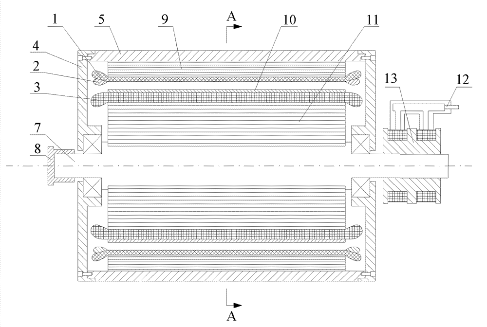
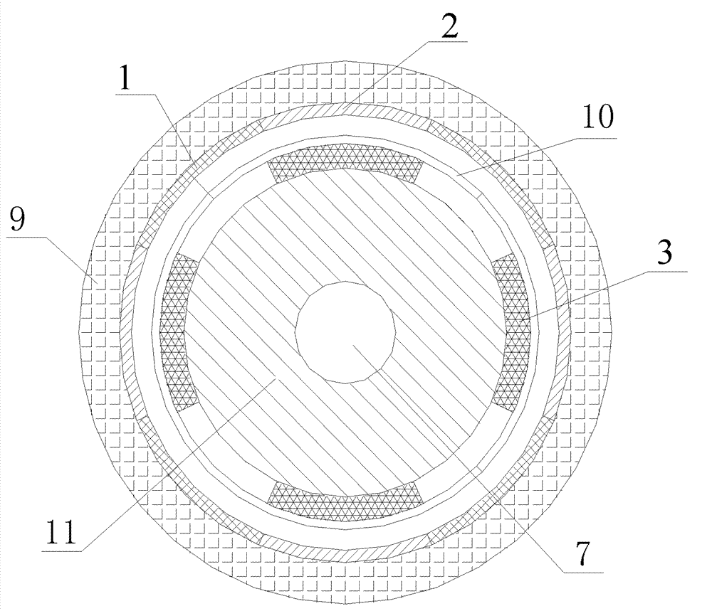
[0022] Specific implementation mode 1: Combination figure 1 with figure 2 To explain this embodiment, the two-phase air-core compensation pulse generator of the present invention includes a stator, a rotor, a clutch 8, a slip ring 12, and a brush 13;

[0023] The stator includes a housing 5, an end cover 4, an air-core stator yoke 9, an A-phase armature winding 1 and a B-phase armature winding 2; the air-core stator yoke 9 is fixed on the inner wall of the housing 5, and the A-phase armature winding The 1 and B phase armature windings 2 are fixed on the inner wall of the hollow-core stator yoke 9, and two end covers 4 are respectively fixed at both ends of the casing 5;

[0024] The rotor includes a main shaft 7, an air-core rotor yoke 11, an excitation winding 3, and a rotor bandage 10. The rotor is arranged in the casing 5 and is concentric with the stator. The air-core rotor yoke 11 is sleeved on the outer surface of the main shaft 7, and the air-core rotor The outer surface of...

specific Embodiment approach 2

[0027] Embodiment 2: This embodiment further defines the two-phase air-core compensation pulse generator described in Embodiment 1. The A-phase armature winding 1 and the B-phase armature winding 2 are arranged alternately along the circumference. The phase A armature winding 1 and the phase B armature winding have an electrical angle difference of 90°.

[0028] The electrical angles of the two-phase armature windings of the motor are arranged orthogonally, and there is no magnetic field coupling. Therefore, the two-phase windings will not induce currents to each other during discharge, and the output current of each phase is relatively independent, which is more conducive to pulse shaping, thereby achieving output Ideal trapezoidal pulse current required by railguns.

specific Embodiment approach 3

[0029] Embodiment 3: This embodiment further defines the two-phase air-core compensated pulse generator described in Embodiment 1. The A-phase armature winding 1 and the B-phase armature winding 2 adopt slotless concentric windings , The coil that composes the winding is composed of multiple strands of Litz wire, which are connected in parallel to form the winding.

[0030] The A-phase armature winding 1 and the B-phase armature winding 2 are wound in parallel with Litz wire, which can effectively reduce the skin effect during discharge, reduce the internal resistance of the motor, and improve the efficiency of the motor; the armature winding coil uses the mold and the ring Oxygen resin molding, epoxy resin plays the role of shaping and strengthening; for windings with no slot structure, it is easier to wind and arrange with concentric winding.


PUM


Abstract

The invention relates to a two-phase hollow-core compensation pulse generator and a method for realizing pulse discharge, and aims to solve the problem that the rotating speed of the conventional hollow-core compensation pulse generator is restricted by the output current pulse width. According to the two-phase hollow-core compensation pulse generator, a stator armature winding adopts a two-phase structure, the electrical angles of the two-phase winding are orthogonally arranged, the output current of each phase is relatively independent, the two phases are parallelly connected and superposed through respective rectifiers and then output pulse currents to a load, and the pulse width is not limited by the semi-period of a motor; during discharging, an excitation winding induces the current to compensate the armature winding, so that the internal inductance of the motor is reduced, and the amplitude of the pulse current is increased; and free components of a load current are eliminated by controlling a triggering angle, and an ideal trapezoidal wave pulse current is output. The two-phase hollow-core compensation pulse generator is used for outputting the pulse current.

Description

Technical field [0001] The invention relates to an air-core compensated pulse generator and a method for realizing pulse discharge, in particular to a two-phase air-core compensated pulse generator and a method for realizing pulse discharge. Background technique [0002] The compensating pulse generator is a special synchronous generator. It uses the principle of magnetic flux compression to compensate the armature windings, reduces the equivalent inductance of the armature windings, and can instantly output extremely large pulse currents, integrating inertial energy storage, electromechanical Energy conversion and pulse forming are integrated. It has the comprehensive advantages of high overall efficiency, high energy density and power density. It is an ideal pulse power source for electromagnetic transmitters. [0003] The new generation of compensating pulse generators widely adopts an air-core structure, and replaces the traditional iron core with a composite material with a hi...

Claims


Application Information

Patent Timeline
Patent Type & Authority Patents(China)
IPC IPC(8): H02P9/06H02K39/00
Inventor 崔淑梅赵伟铎王少飞吴绍朋
Owner HARBIN INST OF TECH
Why Eureka
Try Eureka