
Circular-drying case body of coating machine, drying device and drying assembly line

A technology of circulating drying and drying device, which is applied to the device for coating liquid on the surface, coating, pretreatment surface, etc. It can solve the problems of poor circulation, no guidance, diverting device, low drying efficiency, etc., and achieve the discharge air volume. Consistent, improved drying efficiency, improved uniformity

Inactive Publication Date: 2012-08-22
SHENZHEN HAONENG TECH
View PDF5 Cites 19 Cited by
  • Summary
  • Abstract
  • Description
  • Claims
  • Application Information

AI Technical Summary

Problems solved by technology

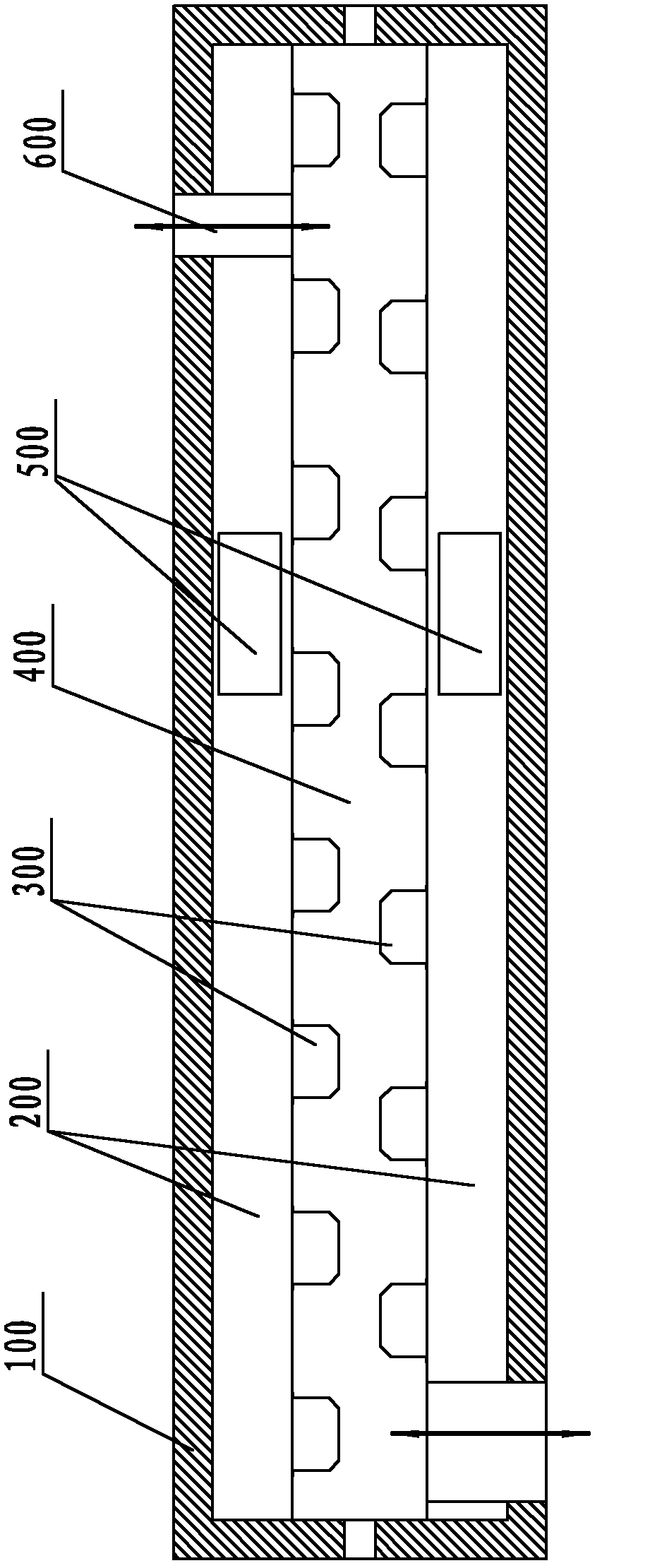
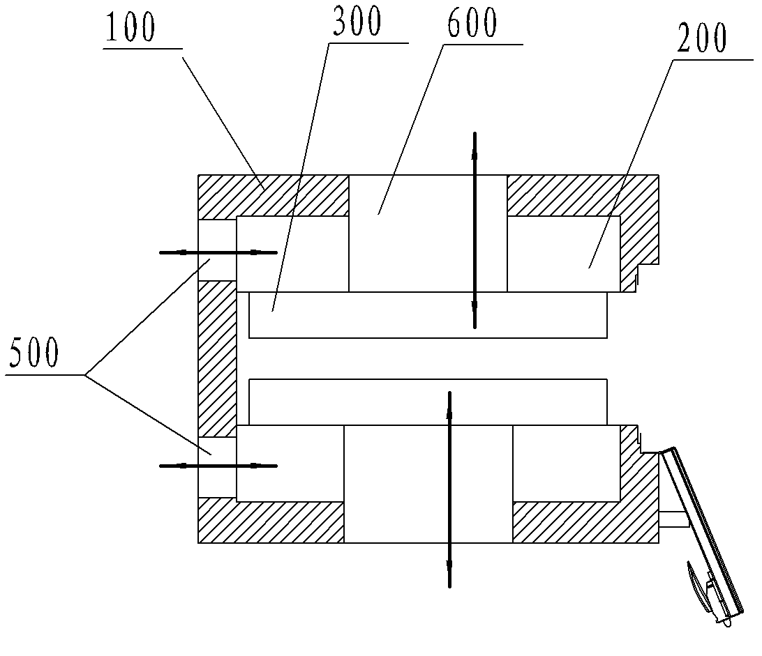
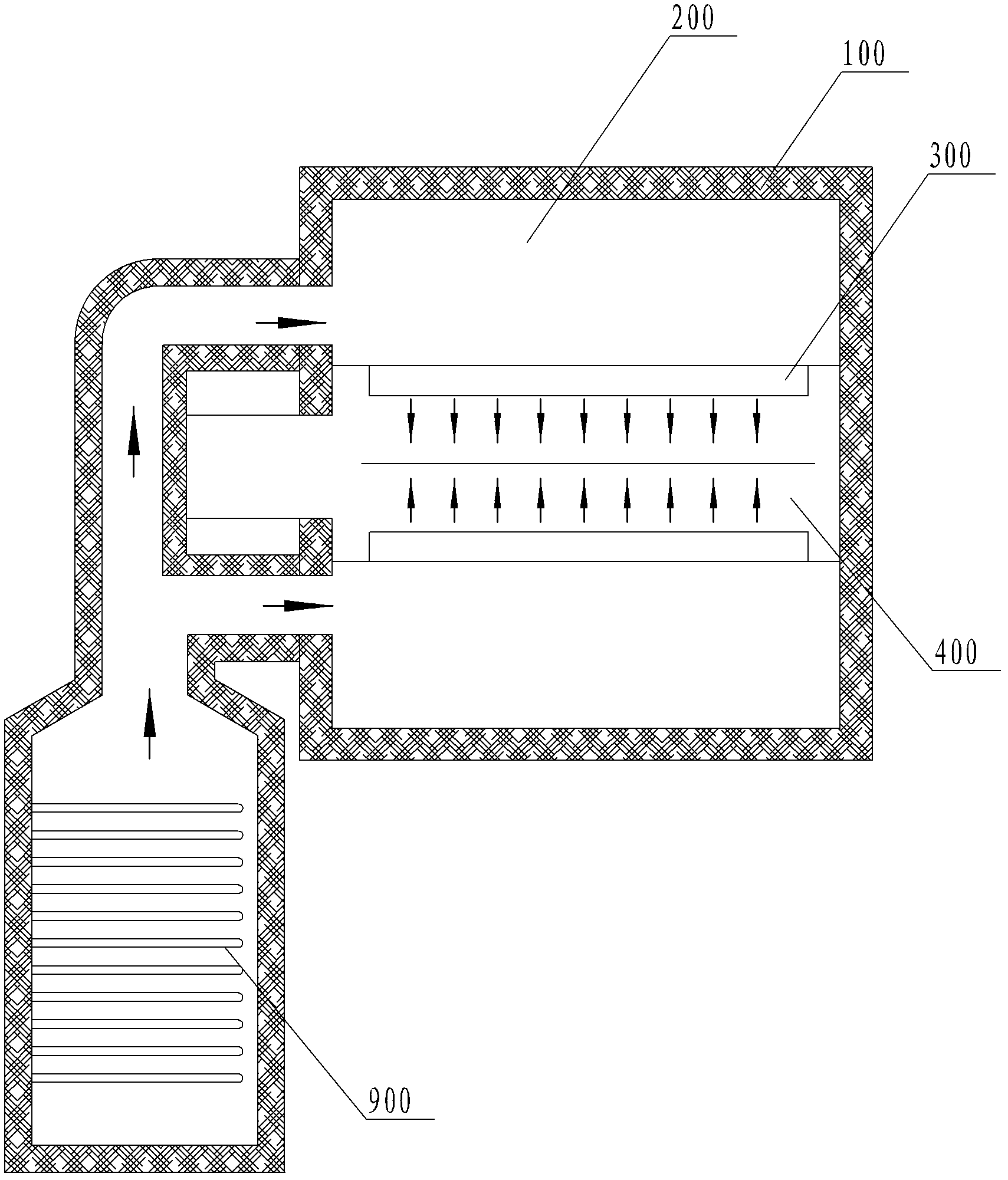
[0003] Most of the existing coatings are simple circulation drying devices, such as Figure 1-3 As shown, an air inlet chamber 200 is formed at the upper and lower intervals inside the oven main body 100, and an air outlet 600 is provided. Between the two air inlet chambers 200 is a drying chamber 400, and the air inlet chamber 200 faces the drying The chamber 400 is provided with an air nozzle 300, and the air inlet chamber 200 is provided with an air inlet pipe 500. The circulation air outlet under the main body 100 of the oven draws out the air through the heater 900 and then returns to the air inlet pipe 500 to form recycling. However, due to its circulation pipe The outlet and the flow channel are shared by the air duct and the exhaust pipe, and the design is unreasonable, resulting in poor circulation, uncontrollable intersection of circulation volume and exhaust air volume, and it is difficult to save energy; in addition, its air inlet directly faces the substrate (painted Cloth products), there is no effective guiding and diverting device, resulting in uneven drying of the product, cracking and curling due to local over-drying, and low drying efficiency; due to poor ventilation, it is easy to cause the concentration of solvent gas inside the box to be too high , leading to equipment alarm shutdown or even fire and explosion

Method used


Image

  • Circular-drying case body of coating machine, drying device and drying assembly line
  • Circular-drying case body of coating machine, drying device and drying assembly line
  • Circular-drying case body of coating machine, drying device and drying assembly line

Examples


Embodiment Construction

[0027] In order to describe the technical content, structural features, achieved goals and effects of the present invention in detail, the following will be described in detail in conjunction with the embodiments and accompanying drawings.

[0028] see Figure 6 as well as Figure 7 , the present invention is a coating machine circulating drying box, which includes an oven main body 1, the oven main body 1 is provided with an air inlet chamber 2, an exhaust chamber 5 and a circulating air chamber 6.

[0029] Among them, the upper and lower parts of the main body of the oven 1 are respectively provided with an air inlet chamber 2, and the main body of the oven 1 is a drying chamber 4 between the upper and lower air inlet chambers 2, and the upper and lower air inlet chambers 2 are provided with a The tuyere 3 of the chamber 4 and the left and right sides of the oven main body 1 are provided with product inlets and outlets 101 corresponding to the drying chamber 4 .

[0030] D...


PUM


Abstract

The invention provides a circular-drying case body of a coating machine, a drying device and a drying assembly line; the circular-drying case body of the coating machine uses an independent inner air chamber; a circular air returning inlet is separated from an air exhaust outlet; a multi-point air discharging method is used so as to process independent control; the drying device is provided with an independent circular blower and an air exhaust blower; a whole guiding and shunting device is designed reasonably according to basic knowledge of fluidics; thus, each air nozzle in the case body has uniform air blowing quantity; pressure is balanced; drying uniformity is improved; therefore, each point of a product is dried synchronously so as to increase drying efficiency.

Description

technical field [0001] The invention relates to a coating supporting device, in particular to a coating machine circulation drying box and a drying device. Background technique [0002] The coating process is widely used in new energy batteries, solar cells, optical films, flexible circuit boards and other industries, and it is also a key process that directly affects product quality. Coating is the process of coating the prepared paste-like viscous slurry evenly, continuously or intermittently on the front and back sides of the substrate (aluminum foil or copper foil), and then drying. The drying effect directly affects The precision of coated products and drying efficiency also directly affect the production efficiency of equipment. [0003] Most of the existing coatings are simple circulation drying devices, such as Figure 1-3 As shown, an air inlet chamber 200 is formed at the upper and lower intervals inside the oven main body 100, and an air outlet 600 is provided. B...

Claims


Application Information

Patent Timeline
Patent Type & Authority Applications(China)
IPC IPC(8): B05D3/04
Inventor 汪正堂
Owner SHENZHEN HAONENG TECH
Learn More