
Junction box

A junction box and wire pair technology, which is applied in the field of junction boxes, can solve the problems of inability to apply decentralized maximum power tracking, increase the difficulty of the internal circuit of the junction box, increase the cost, etc., and achieve easy installation and maintenance, simple structure, and space saving. Effect

Inactive Publication Date: 2012-08-22
DELTA ELECTRONICS INC
View PDF4 Cites 2 Cited by
  • Summary
  • Abstract
  • Description
  • Claims
  • Application Information

AI Technical Summary

Problems solved by technology

[0005] However, the existing electrical connection mechanism of the junction box cannot meet the requirements of distributed maximum power tracking (Distributed MPPT, DMPPT) technology, and because the electrical connection mechanism in the junction box has positive and negative output terminals, it is desired to transmit through the electrical connection mechanism If the power supply is connected to the power output terminal of the junction box, a wiring circuit must be added in the junction box to electrically connect the positive output terminal of the electrical connection mechanism to the positive output terminal of the junction box, and electrically connect the negative output terminal of the electrical connection mechanism. To the negative output of the junction box
Adding a wiring circuit in the junction box not only complicates the structure and increases the difficulty of the internal circuit of the junction box, but also increases the cost

Method used


Image

  • Junction box
  • Junction box
  • Junction box

Examples


Embodiment Construction

[0060] Some typical embodiments embodying the features and advantages of the present invention will be described in detail in the following description. It should be understood that the present invention can have various changes in different ways, which do not depart from the scope of the present invention, and the descriptions and drawings therein are essentially for illustrative purposes rather than limiting the present invention.

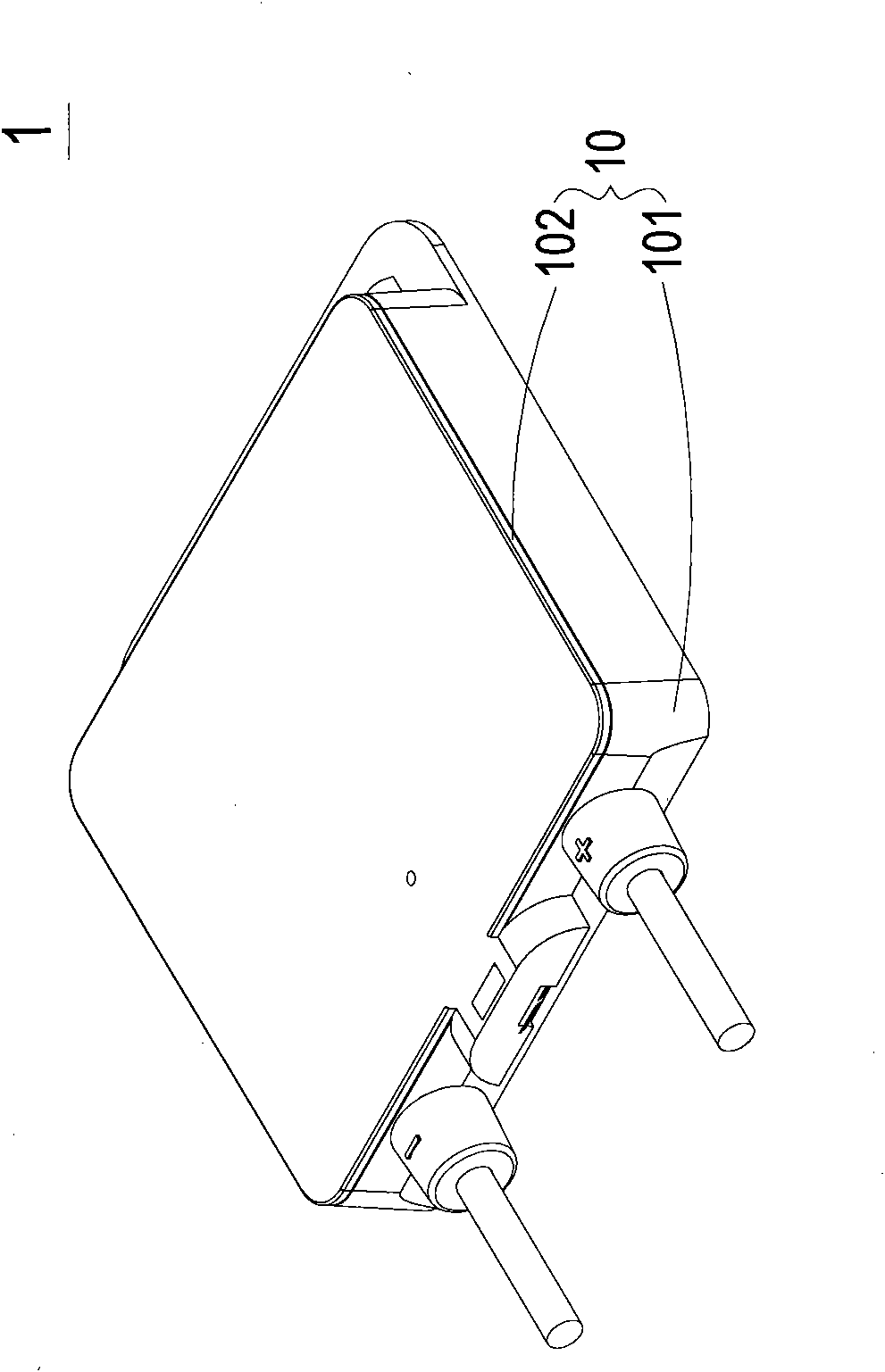
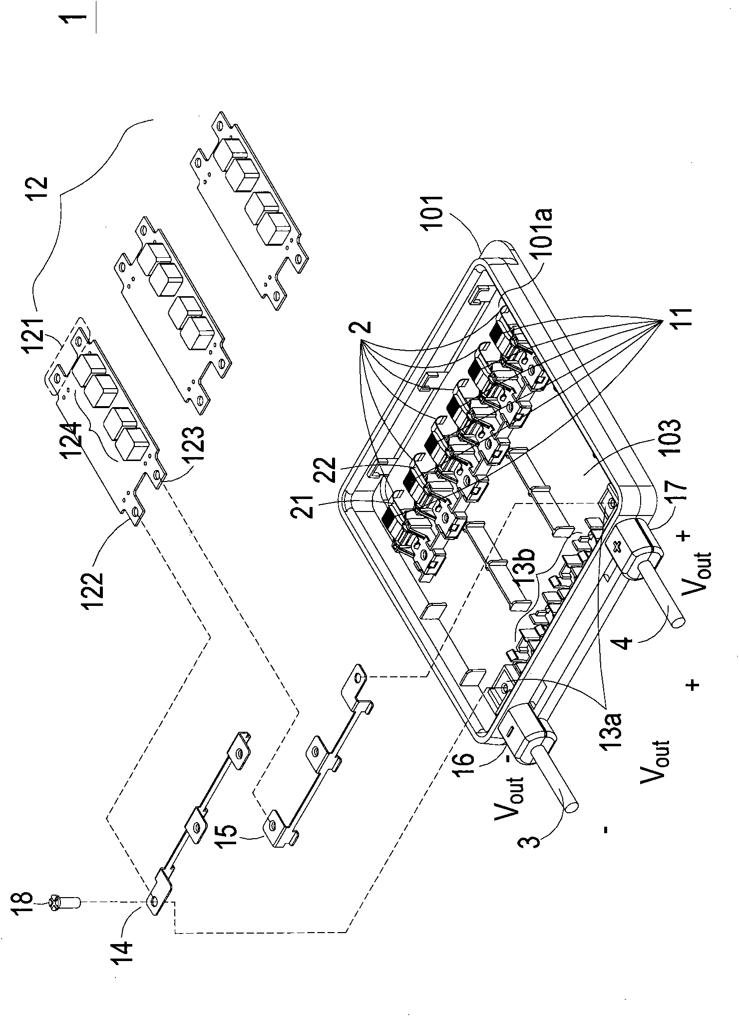
[0061] See figure 1 , Which is a schematic diagram showing the appearance structure of a junction box applied to a solar module according to a preferred embodiment of the present invention. The structure of the junction box 1 of the present invention includes a housing 10 made of durable plastic, which can withstand the influence of all external weather factors and is guaranteed for at least 20 years, and also has the characteristics of insulation. The housing 10 includes a base 101 and an upper cover 102, and the detachable upper cover 102 can be f...


PUM


Abstract

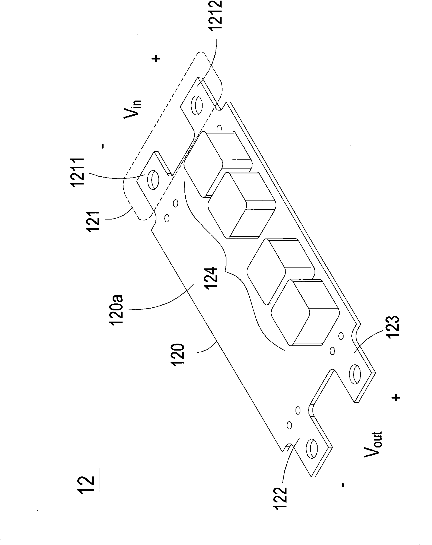
The invention provides a junction box which comprises a shell, a plurality of wire connectors, a plurality of power supply changeover units, a first guide part element and a second guide element, wherein the shell is provided with an opening and used for introducing a plurality of wire pairs through the opening; the shell is provided with a first power output end and a first power output end; the wire connectors are arranged in the shell and used for connecting with the multiple wire pairs; the power supply changeover units are detachably connected with the wire connectors; each power supply changeover unit is provided with a first guide part and a second guide part; the first guide element is connected with the first guide parts of the power supply changeover units and the first power output end; and the second guide element is connected with the second guide parts of the power supply changeover units and the second power output end. The electric connection mechanism provided by the invention has the advantage of simple structure, has cost benefit, and is easier for installation and maintenance.

Description

Technical field [0001] The invention relates to a junction box, in particular to a junction box applied to solar or photovoltaic modules. Background technique [0002] Because photovoltaic solar energy has many advantages, it has become one of the most promising renewable energy sources in the world today. Basically, photovoltaic solar energy is freely available, it does not require fuel, does not generate waste or pollution, and the solar generator it uses requires only a small amount of effort to maintain, and it can be used continuously at low operating costs without special management20 To 30 years. On the other hand, solar generators can also be easily installed in general homes, schools or business premises, and there is no need for special handling construction or additional floor space at the location where they are equipped with assembly equipment. Safe and quiet operation. In remote areas, it is easier to construct a system of the required size to produce its own sup...

Claims


Application Information

Patent Timeline
Patent Type & Authority Applications(China)
IPC IPC(8): H01L31/048H02S40/34
CPCY02E10/50
Inventor 黄金柱游承谕黄仁德
Owner DELTA ELECTRONICS INC
Learn More