Guiding high-strength dual-waveband directional antenna

A directional antenna, dual-band technology, applied to antennas, antennas suitable for movable objects, devices that make antennas work in different bands at the same time, etc., can solve the problems of no antenna system, low structural strength, large size, etc., Achieve the effect of improving overall strength, small in-band differential loss, and improving bandwidth

Active Publication Date: 2012-08-22
CETC YANGZHOU BAOJUN ELECTRONICS +2
View PDF6 Cites 2 Cited by
  • Summary
  • Abstract
  • Description
  • Claims
  • Application Information

AI Technical Summary

Problems solved by technology

[0004] Existing antennas either can only work in Western systems or in Eastern systems, and there is no antenna system compatible with both systems, and the radome of this type of antenna is not formed by mold casting. The disadvantages are low structural strength, large size, narrow bandwidth, low gain, and can only work in one band

Method used


Image

  • Guiding high-strength dual-waveband directional antenna
  • Guiding high-strength dual-waveband directional antenna
  • Guiding high-strength dual-waveband directional antenna

Examples


Embodiment Construction

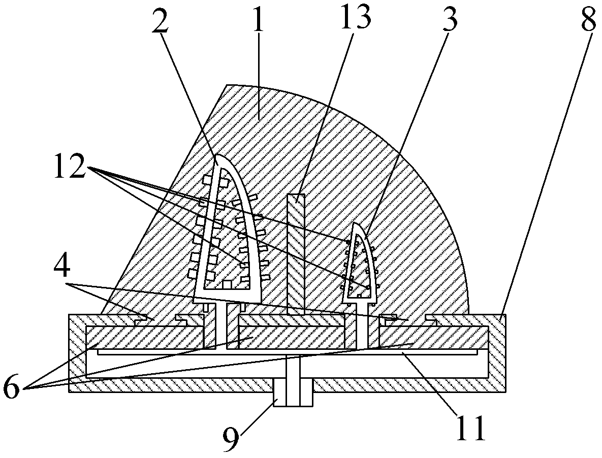
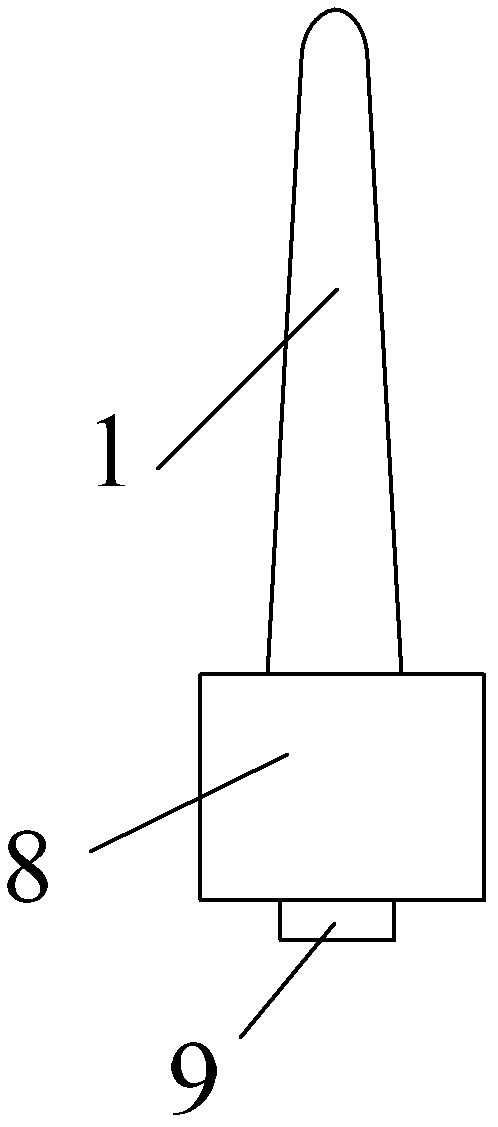
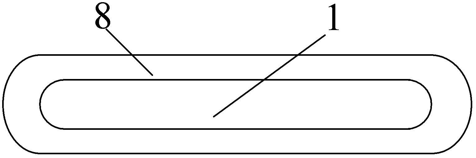
[0031] A guiding type high-intensity dual-band directional antenna includes: a metal reflection cavity 8, a microstrip plate 6 is arranged in the metal reflection cavity 8, a multiplexer 11 is arranged on the microstrip plate 6, and a multiplexer 11 The coaxial cable 9 is connected to the main path 11-3 of the multiplexer 11, and the first radiation oscillator 2 and the second radiation oscillator 3 are respectively connected to the first branch 11-1 and the second branch 11-2 of the multiplexer 11. , the first radiating vibrator 2 and the second radiating vibrator 3 are covered with a solid radome 1, and a guiding vibrator 13 is arranged inside the solid radome 1, and the guiding vibrator 13 is located between the first radiating vibrator 2 and the second radiating vibrator. Between the radiating oscillators 3, the height of the guiding oscillator 13 is between the first radiating oscillator 2 and the second radiating oscillator 3, and the lower end of the guiding oscillator 1...


PUM


Abstract

A guiding high-strength dual-waveband directional antenna comprises a metal reflection cavity. A micro-strip plate is arranged in the metal reflection cavity, a multiplexer is arranged on the micro-strip plate, a coaxial cable is connected to a main path of the multiplexer, a first radiation oscillator and a second radiation oscillator are connected to a first branch and a second branch of the multiplexer respectively and covered by a solid antenna cover, and the first radiation oscillator and the second radiation oscillator are hollow sail-shaped monopole metal oscillators. Each hollow sail-shaped monopole metal oscillator comprises a first metal straight strip, a second metal straight strip and an arc metal strip, which are in end-to-end connection and form three acute angles, metal blocks are arranged on or directly welded to the hollow sail-shaped monopole metal oscillators to form inner and outer battlement structures.

Description

technical field [0001] The invention relates to an inner and outer battlement-type directing type high-strength dual-band directional antenna suitable for flight carriers. Its typical working frequency bands are P-band and L-band, and it works with vertical polarization. It has high gain, small standing wave, high efficiency, Dual-band work is mainly used in identification systems and communication systems for various flight carrier identities. Background technique [0002] At present, civil aviation systems have installed identification systems that are convenient for air traffic control; various military fighter planes in developed countries in Europe and the United States are equipped with identification friend or foe systems based on Western systems, and their main working band is L-band; Military fighter planes are equipped with an identification friend or foe system based on the Eastern system, and its main working band is the P band; while some working fighter planes ...

Claims


Application Information

Patent Timeline
Patent Type & Authority Applications(China)
IPC IPC(8): H01Q1/36H01Q1/42H01Q5/01H01Q19/00H01Q19/10H01Q1/28H01Q5/10
Inventor 曹振新夏继钢王安宁沙本桂
Owner CETC YANGZHOU BAOJUN ELECTRONICS
Why Eureka
Try Eureka