
Evaporative condensing and cooling device

An evaporative condensation and evaporative cooling technology, which is applied in the direction of fixed conduit components, heat exchanger types, lighting and heating equipment, etc., can solve the problems of water mist environment, pollution, etc., to reduce the air velocity and eliminate the growth of Legionella Effect

Active Publication Date: 2012-08-29
上海与进智能科技有限公司
View PDF10 Cites 13 Cited by
  • Summary
  • Abstract
  • Description
  • Claims
  • Application Information

AI Technical Summary

Problems solved by technology

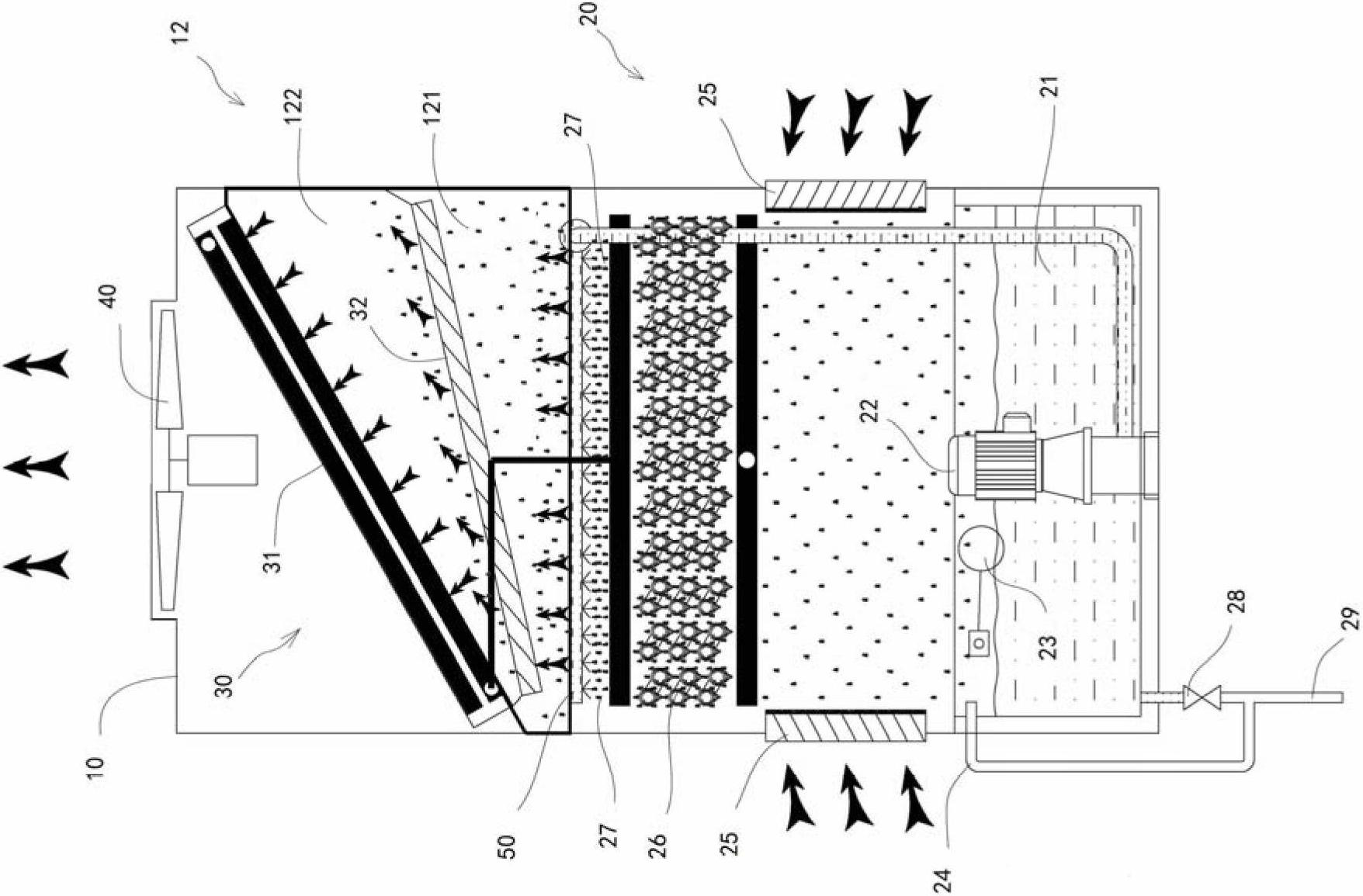
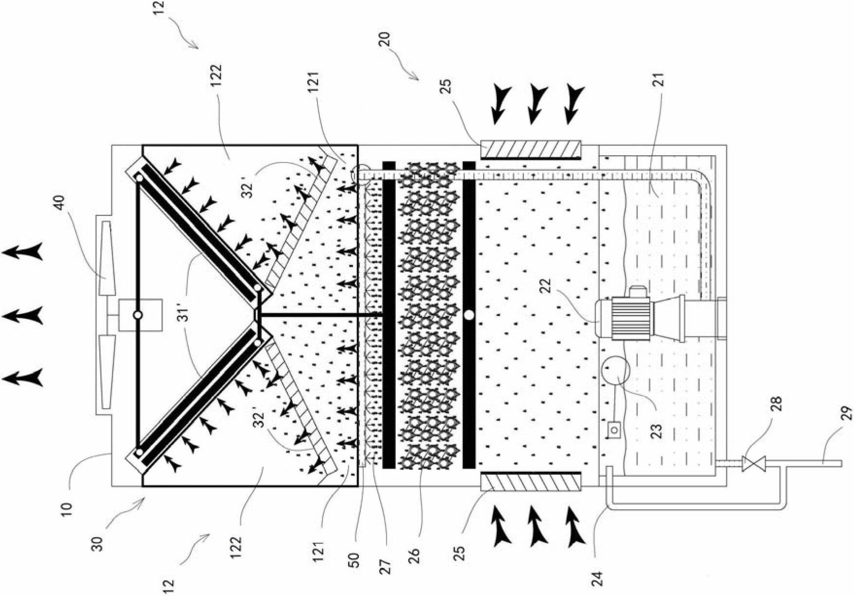
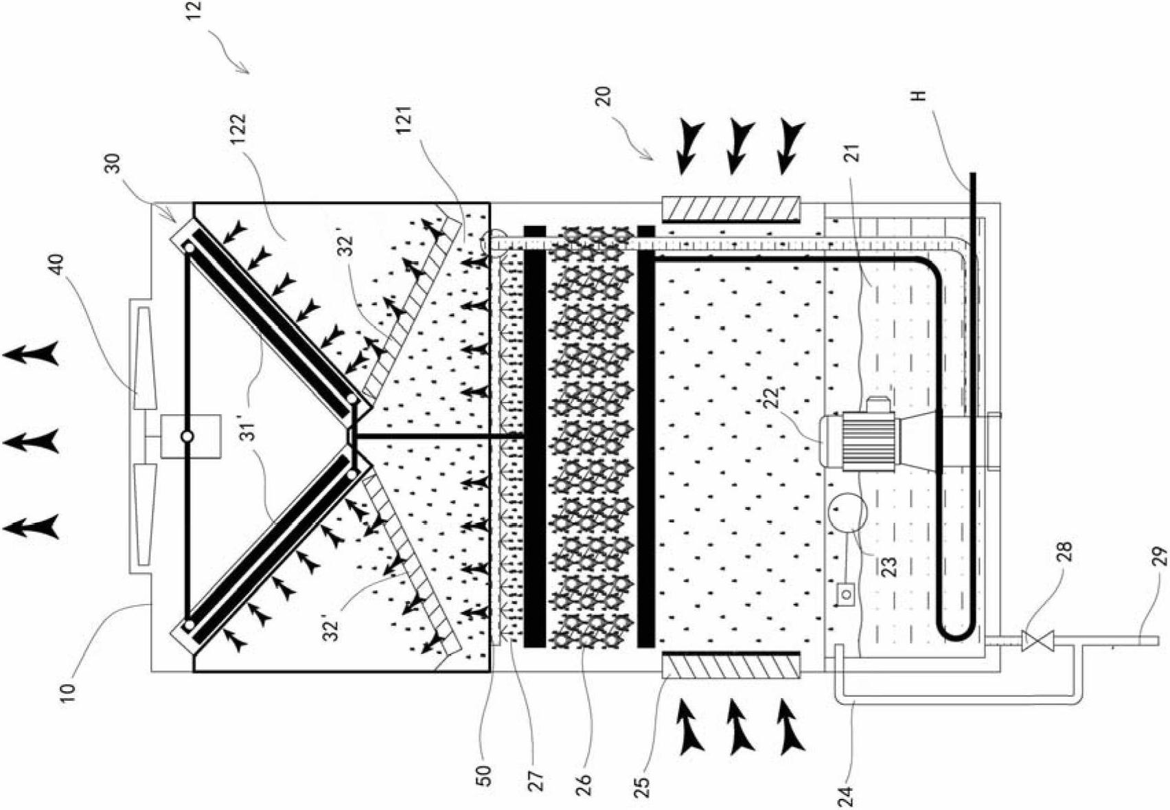
[0020] The purpose of the present invention is to provide a new type of evaporative condensation and cooling device. A heat exchanger for demisting is provided above the evaporative condensation or cooling device, and the demisting device is arranged in the static pressure box. , change the wind direction, separate the steam and water and fully evaporate the saturated water vapor, solve the problem of water mist generated during the operation of the evaporative condensation and cooling device and cause pollution to the environment

Method used


Image

  • Evaporative condensing and cooling device
  • Evaporative condensing and cooling device
  • Evaporative condensing and cooling device

Examples


Embodiment approach

[0060] It can be seen from the previous overall implementation that the evaporative cooling heat exchanger in the upper section of the energy-saving fog-free evaporative condensation and cooling device uses the saturated water vapor generated by the lower evaporative condensation and cooling heat exchanger during the heat exchange process. And through the evaporative cooling heat exchanger in the upper section, the superheated steam is cooled into saturated gas, or the temperature of the high-temperature liquid is effectively reduced. This part of heat accounts for about 20-30% of the total heat exchange of the device, that is, the evaporative condensation and cooling exchange in the lower section The heat load of the heater is reduced by 20~30%. Since the circulating water volume and circulating air volume of the evaporative condensation and cooling device are calculated based on the evaporation, condensation and cooling heat transfer in the lower section, the circulating water...


PUM


Abstract

The invention relates to an evaporative condensing and cooling device, which comprises a tank body divided into an upper segment and a lower segment, an air inlet and an air outlet, wherein the area of the inner section of the upper segment is larger than the area of the inner section of the lower segment, so as to enable the upper segment of the whole tank body to form a static pressure tank; an evaporative condensing unit formed by a water collecting tank, a first heat exchanger, a spraying device and a water pump is arranged at the inner part of the lower segment of the tank body; a demisting component comprising a second heat exchanger connected in series with an outlet of the first heat exchanger and a wind direction deflecting plate is arranged in the static pressure tank at the upper segment of the tank body; the evaporative condensing and cooling device further comprises a fan arranged in position suitable for providing negative pressure for the evaporative condensing device; air is enabled to enter the tank body from the air inlet at a low first speed, and rises through the first heat exchanger of the evaporative condensing unit, so that saturated water vapor entrained with water drops enters the static pressure tank to be subject to water-vapor separation; and then moisture in the saturated water vapor is evaporated by the second heat exchanger in the demisting component, and the water vapor becomes gas with humidity not higher than the environmental humidity nearby the air outlet and is then discharged from the air outlet, thereby avoiding a water mist problem from occurring around the device.

Description

technical field [0001] The invention relates to evaporative condensation and cooling technology, in particular to an evaporative condensation and cooling device with a demisting device, which can prevent the evaporative condensation and cooling device from discharging saturated water vapor during condensation or cooling, and eliminate the The environment causes the problem of water mist pollution. Background technique [0002] In condensation and cooling technology, cooling devices (such as cooling towers) and condensing devices (such as condensers) are often used in combination. The principle is to use the temperature difference between the cooling medium and the cooled medium to conduct heat through the heat exchanger. The purpose of cooling or condensing the cooled medium through mass exchange. For example, in refrigeration and air-conditioning systems, the high-pressure superheated refrigerant gas in the condenser transfers heat to the relatively low-temperature cooling...

Claims


Application Information

Patent Timeline
IPC IPC(8): F28D5/02F28D1/02
Inventor 刘玉岭黄文斐崔国栋刘方然
Owner 上海与进智能科技有限公司
Learn More