Constant-speed blurred image construction method and device based on splicing of two frames of static images
A technology for blurred images and static images, applied in image analysis, image data processing, instruments, etc., can solve the problems of reducing experiment difficulty and experiment cost
- Summary
- Abstract
- Description
- Claims
- Application Information
AI Technical Summary
Problems solved by technology
Method used
Image

Examples
example 1
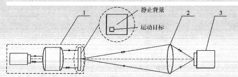
[0082] figure 1 It is a structural schematic diagram of a uniform-velocity fuzzy image construction device based on two-frame static image stitching. A substitute target 1, a substitute optical system 2, and an image sensor 3 are sequentially arranged along the direction of light propagation, and the substitute target 1 is imaged to the surface of the image sensor 3 through the substitute optical system 2, and the substitute target 1 of the device includes a static background and a moving Two parts of the target, wherein, the static background covers the entire field of view of the substitute optical system 2, and the moving target can perform two-dimensional movement in the direction perpendicular to the optical axis of the device within the range of the field of view of the substitute optical system 2; Two-dimensional movement in the direction vertical to the optical axis of the device within the field of view.
[0083] The following two embodiments are all corresponding to...
example 2
[0111] This example will figure 1 The substitute target 1 in is replaced by a point target, and the rest of the components and parameters are exactly the same.
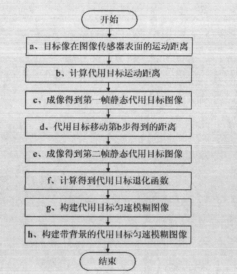
[0112] A method for constructing a uniform blurred image based on stitching two frames of static images, comprising the following steps:
[0113] a. In a real scene, according to the movement speed v of the point target 1 =680m / s, the exposure time t of the image sensor 3 1 =50ms, and the lateral magnification of the optical system β 1 =-10 -5 , to obtain the movement distance of the point target image on the surface of the image sensor 3: d=v 1 ·t 1 ·β 1 =680×50×10 -3 ×(-10 -5 )=-340μm;
[0114] b. In the simulated scene, according to the lateral magnification β of the substitute optical system 2 2 =-0.0557, using the moving distance d=340 μm of the point target image obtained in the first step on the surface of the image sensor 3 to obtain the moving distance d of the substitute point target 1 between two im...
PUM
 Abstract
Description
Claims
Application Information