

White light electrogenerated light-emitting apparatus
An electroluminescent device and electroluminescent technology, applied in the direction of electro-solid devices, luminescent materials, electrical components, etc., can solve the problems of restricting blue light emission, rising device temperature, poor life and stability, etc., so as to improve the luminescence The effect of efficiency
- Summary
- Abstract
- Description
- Claims
- Application Information
AI Technical Summary
Problems solved by technology
Method used
Image

Examples
Embodiment 1
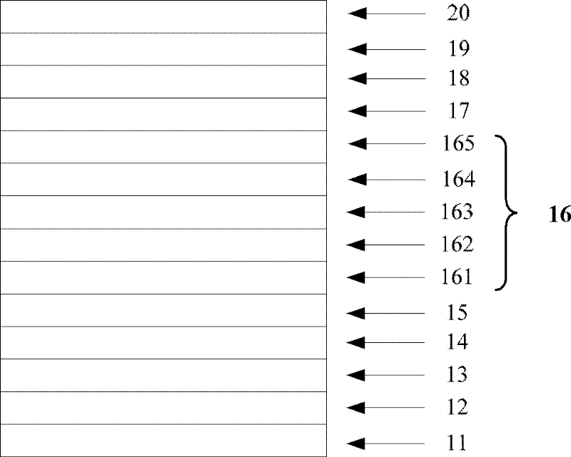
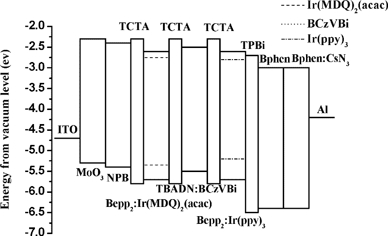
[0038] A white light electroluminescent device, its structure is: glass / ITO / MoO 3 / NPB / TCTA / Bepp 2 :Ir(MDQ) 2 (acac) / TCTA / TBADN:BCzVBi / TCTA / Bepp 2 :Ir(ppy) 3 / TPBi / Bphen / Bphen:CsN 3 / Al.
[0039] Regarding the white photoluminescent device in this example, according to its structure, and using evaporation technology, each organic functional layer is prepared by evaporation in sequence; wherein, in the composite structure of the light-emitting layer: the red light of the red phosphorescence light-emitting layer The material is Ir(MDQ) 2 (acac), the dopant host is Bepp 2 , the doping ratio of the red light material is 0.5%, and the thickness is 7nm; the material of the first spacer layer is TCTA, and the thickness is 2nm; the blue light material of the blue fluorescent layer is BCzVBi, the main body is TBADN, and the doping ratio of the blue light material is 10%, The thickness is 10nm; the material of the second spacer layer is TCTA, and the thickness is 2nm; the green l...
Embodiment 2
[0047] A white light electroluminescence device, its structure is: glass / ITO / WO 3 / TPD / TCTA / BeBq 2 :Ir(piq) 2 (acac) / TPD / TPD:BCzVB / TPD / BeBq 2 :Ir(ppy)2(acac) / TAZ / TPBI / Cs 2 CO 3 / Al.
[0048] Regarding the white photoluminescent device in this example, according to its structure, and using evaporation technology, each organic functional layer is prepared by evaporation in sequence; wherein, in the composite structure of the light-emitting layer: the red light of the red phosphorescence light-emitting layer The material is Ir(piq) 2 (acac), the doping host is BeBq 2 , the doping ratio of the red light material is 5%, and the thickness is 5nm; the material of the first spacer layer is TPD, and the thickness is 10nm; the blue light material of the blue fluorescent layer is BCzVB, the main body is TPD, and the doping ratio of the blue light material is 20%, The thickness is 20nm; the material of the second spacer layer is TPD, and the thickness is 10nm; the green light mate...
Embodiment 3
[0050] A white electroluminescent device, its structure is: glass / ITO / VO x / TDAPB / NPB / BeqQ 2 :Ir(piq) 3 / NPB / TCTA:TBPe / TDAPB / BeMQ 2 :Ir(ppy) 3 / BND / TPQ / LiF / Al.
[0051] Regarding the white photoluminescent device in this example, according to its structure, and using evaporation technology, each organic functional layer is prepared by evaporation in sequence; wherein, in the composite structure of the light-emitting layer: the red light of the red phosphorescence light-emitting layer The material is Ir(piq) 2 (acac), the doping host is BeqQ 2 , the doping ratio of the red light material is 4%, the thickness is 15nm; the material of the first spacer layer is NPB, the thickness is 1nm; the blue light material of the blue fluorescent layer is TBPe, the main body is TCTA, the doping ratio of the blue light material is 15%, the thickness is The material of the second spacer layer is TDAPB, and the thickness is 1nm; the green light material of the green phosphorescence emittin...
PUM
| Property | Measurement | Unit |
|---|---|---|
| Thickness | aaaaa | aaaaa |
| Thickness | aaaaa | aaaaa |
| Thickness | aaaaa | aaaaa |
Abstract
Description
Claims
Application Information