
Realization method of air gap clad optical fiber

A technology of air gap and implementation method, which is applied in cladding optical fibers, multi-layer core/cladding optical fibers, optical waveguides and light guides, etc. problem, to achieve the effect of mature technology, lower production cost and simple production process

Inactive Publication Date: 2012-09-05
TXSTAR LASER TECH SHANGHAI CO LTD
View PDF7 Cites 7 Cited by
  • Summary
  • Abstract
  • Description
  • Claims
  • Application Information

AI Technical Summary

Problems solved by technology

The inner cladding of the air-clad optical fiber arranged with air holes is circular, and the coupling efficiency of the pump light is low; because there are many contact points, the loss of the optical fiber is large; the manufacturing process of the photonic crystal optical fiber preform is complicated, especially the prefabrication of the capillary-assembled optical fiber The technical difficulty of the stick is high, the yield rate is low, the production cost is high, and it is difficult to realize industrial production

Method used


Image

  • Realization method of air gap clad optical fiber
  • Realization method of air gap clad optical fiber
  • Realization method of air gap clad optical fiber

Examples


Embodiment Construction

[0018] The present invention will be described in further detail below in conjunction with the accompanying drawings and embodiments.

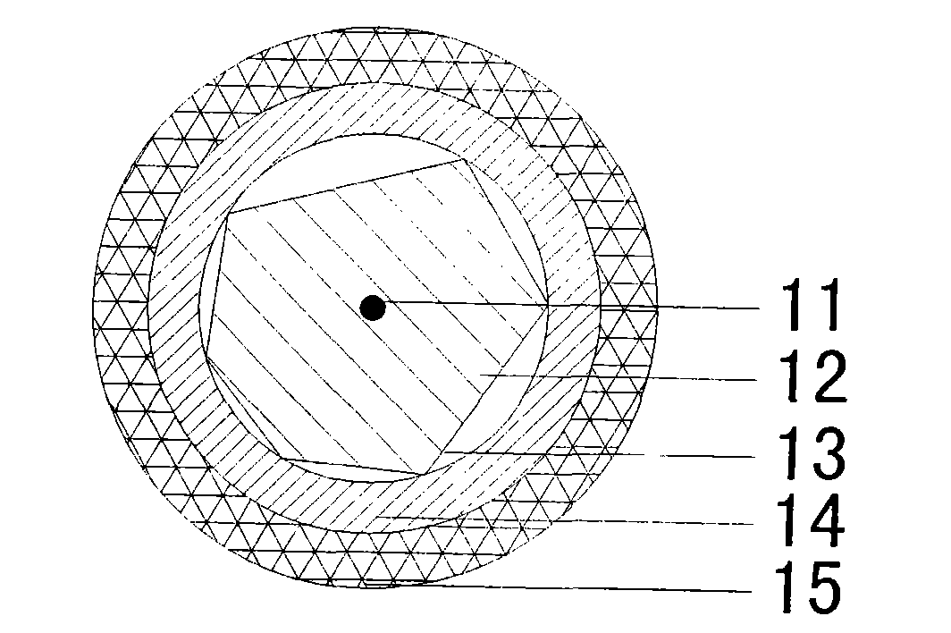
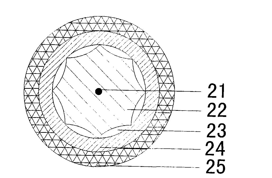
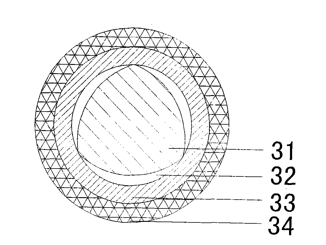
[0019] attached figure 1 It is the heterohexagonal straight-sided air cladding ytterbium-doped double-clad optical fiber of the first embodiment of the present invention, the periphery of the ytterbium-doped fiber core 11 is a pure silica hexagonal inner cladding 12, and the outer cladding 12 is an air cladding layer 13, followed by an inner protective layer 14 of quartz over which is covered an outer protective layer 15 of UV-cured acrylic resin. In this embodiment, the MCVD process and the high-temperature gas-phase doping process are used to manufacture the ytterbium-doped fiber core inner cladding preform, the rod diameter is 32mm, and the length is 500mm; then the fiber core inner cladding preform is formed into a heterohexagon by optical cold processing A quartz tube is placed on the core preform as the inner protective layer 14, with a...


PUM


Abstract

The invention relates to a double-clad active optical fiber. Aiming at the defects in the prior art, the invention provides a realization method of an air gap clad optical fiber. The realization method adopts air as an optical cladding layer and adopts a core layer with a novel structure, so that the realization method can be used for improving an energy transmitting optical fiber or a photonic crystal optical fiber of an air cladding layer; the manufacturing process is simplified, the manufacturing cost is reduced and the pumping coupling efficiency is improved. The realization method is characterized in that the optical fiber is formed by a core layer with a polygonal section, the air cladding layer, an inner protection layer with a circular section, and an outer protection layer with a circular section in sequence from inside to outside; the core layer is connected with the inner wall of the inner protection layer with the circular section through the top of a polygonal structure; and an air gap between the inner protection layer and the core layer is the air cladding layer of the optical cladding layer. The double-clad active optical fiber solves the problem of low numerical pore diameters of the conventional high-energy transmission optical fiber and a double-clad optical fiber, and the high-temperature resistance of a low-refractive-index coating material, can improve the structure and the performance of the air cladding layer of the photonic crystal optical fiber, improves the optical fiber production efficiency, and greatly propels application of the optical fiber on the aspects of kilowatt and myriawatt high-energy transmission, a high-power laser system and the like.

Description

technical field [0001] The present invention relates to double-clad active optical fibers. technical background [0002] The double-clad active fiber and the energy-transmitting fiber of the corresponding size are the core components of high-power fiber lasers and amplifiers. The numerical aperture of the inner cladding and core of the fiber and the performance of the outer cladding material directly affect the high-power laser transmission capability of the fiber. . [0003] The CN95194426.6 patent of Polaroid Corporation of the United States discloses the design principle of double-clad optical fiber. The optical cladding material of double-clad optical fiber uses quartz glass or low-refractive index coating as the outer cladding, which can realize the transmission of pump light in the inner cladding of the optical fiber and improve Fiber output power. The numerical aperture of the inner cladding of this double-clad active optical fiber is up to about 0.46. The optical f...

Claims


Application Information

Patent Timeline
IPC IPC(8): G02B6/036G02B6/02
Inventor 潘志勇
Owner TXSTAR LASER TECH SHANGHAI CO LTD
Learn More