Method for operating an industrial process

An output operation, plasma technology, applied in the direction of output power conversion device, discharge tube, electrical components, etc., to reduce temperature fluctuations and reduce temperature drop

Active Publication Date: 2012-09-05
HUETTINGER ELEKTRONIK
View PDF2 Cites 2 Cited by
  • Summary
  • Abstract
  • Description
  • Claims
  • Application Information

AI Technical Summary

Problems solved by technology

However, between two stages of power operation, t...

Method used


Image

  • Method for operating an industrial process
  • Method for operating an industrial process
  • Method for operating an industrial process

Examples


Embodiment Construction

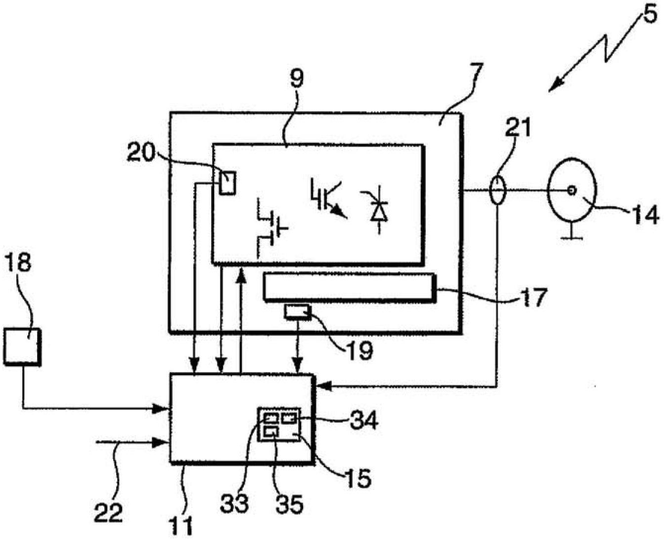
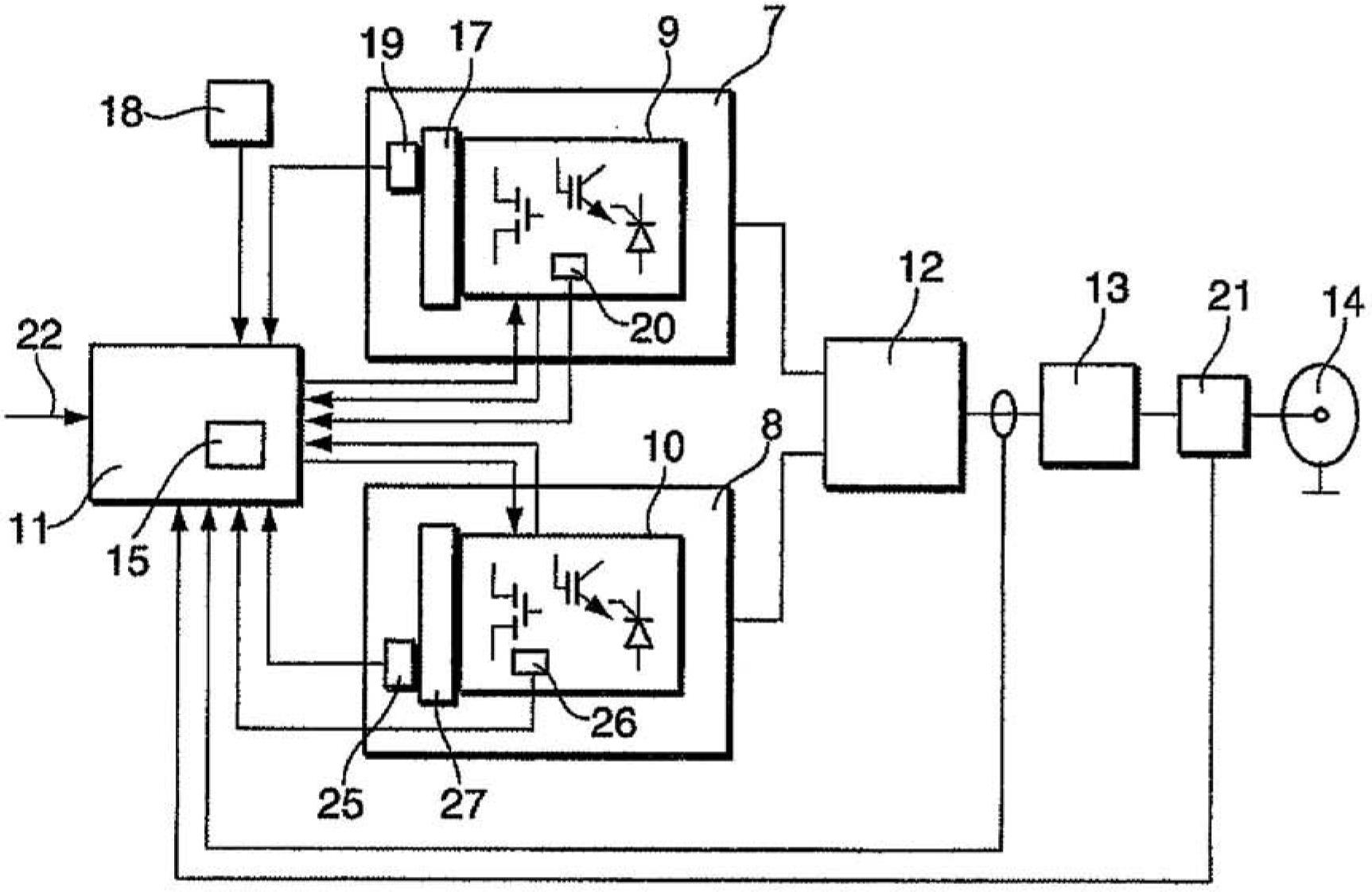
[0055] figure 1 An alternating current power generating device 5 is shown, which may be a high frequency power generating device. The AC power generating device 5 has a power converter unit 7 in which at least one semiconductor switching element 9 is arranged. The semiconductor switching element 9 is here represented by three different symbols for three frequently used semiconductor switching elements (MOSFET, IGBT, SCR), and is intended to be understood in such a way that in this example includes All possible semiconductor switching elements connected in different ways. The power converter unit 7 can have, for example, a half bridge or a full bridge, a class E inverter or a class D inverter. The semiconductor switching element 9 can be cooled with a cooling device 17 . For example, the cooling device 17 may be a cooling component that releases heat to air or a liquid cooling medium. The semiconductor switching element 9 is controlled by a control circuit 11 . The generat...


PUM


Abstract

The invention relates to a method for operating a plasma system, an induction heating system, or a laser excitation system in a pulsed power output mode, wherein a first power POUT1.1 is generated in a power output time period [delta]T1, and is output at a power output of a power generator for providing power to a plasma process, of an induction heating process, or of a laser excitation process, and no power POUT2.1 suitable for igniting or operating a plasma process, an induction process, or a laser excitation process is output at the power output of the power generator in a pulse pause time period [delta]T2, in that at least one semiconductor circuit element (9) of the power generator is actuated, wherein a first loss power PV1 is generated in the at least one semiconductor circuit element (9) at the same time as the generation of the first power Pout1.1 during the power output time period [delta]T1, and a second loss power PV2 is generated in the at least one semiconductor element (9) during the pulse pause time period [delta]T2, and the generated loss powers PV1, PV2 are converted into heat, wherein a drop in temperature of the semiconductor circuit element (9) by greater than a predefined value is prevented by suitably actuating the semiconductor circuit element, and the power output mode and the pulse pause mode alternate continuously.

Description

technical field [0001] The invention relates to a method for operating a plasma device, an induction heating device or a laser excitation device. Background technique [0002] To generate AC power, especially high-frequency power, for industrial processes such as induction heating or plasma excitation or excitation of gas lasers, AC power generation devices with amplifier tubes are still often used at high power levels. This is due in particular to the robust behavior of the amplifier tube against rapid load changes. However, such an AC power generating device having an amplifier tube has a low level of efficiency, and the amplifier tube suffers losses. Therefore, attempts have been increasingly made to replace these AC power generating devices with devices operating with semiconductor switching elements. These semiconductor switching elements can be transistors, for example. Power levels up to about 500W per transistor can be generated with currently available transistor...

Claims


Application Information

Patent Timeline
IPC IPC(8): H01J37/32H05B6/02H05H1/46H02M1/32
CPCH01J37/32H02M1/32H02M7/53871H05B6/06H05H1/46H05B6/02
Inventor C·托默M·格吕克
Owner HUETTINGER ELEKTRONIK
Why Eureka
Try Eureka