Wrinkle type apodization waveguide Bragg grating filter and manufacturing method thereof

A technology of waveguide Bragg and grating filter, which is applied in the direction of optical waveguide lightguide, coupling of optical waveguide, cladding optical fiber, etc., can solve the problems of affecting communication quality, failing to meet the requirements of high reflectivity, and difficult to realize the process, etc., to achieve Improve the side mode suppression ratio, high side mode suppression ratio, and reduce the effect of influence

Inactive Publication Date: 2013-10-30
SOUTHEAST UNIV
View PDF6 Cites 0 Cited by
  • Summary
  • Abstract
  • Description
  • Claims
  • Application Information

AI Technical Summary

Problems solved by technology

When the integrated waveguide Bragg grating filter is set with proper parameters, high reflectivity can be obtained, but high side lobes appear together with high reflectivity, and high Bragg grating filter side lobes will cause damage to adjacent channels in communication systems Very large crosstalk, affecting communication quality
If some apodization methods reported in the literature are used to remove the side lobes of the waveguide grating filter to improve the side-mode suppression ratio, the partial apodization method is complicated and difficult to implement, and it will suppress the main peak reflectivity while improving the side-mode suppression ratio. System requirements for high reflectivity

Method used


Image

  • Wrinkle type apodization waveguide Bragg grating filter and manufacturing method thereof
  • Wrinkle type apodization waveguide Bragg grating filter and manufacturing method thereof
  • Wrinkle type apodization waveguide Bragg grating filter and manufacturing method thereof

Examples


Embodiment Construction

[0028] The technical solution of the present invention will be described in detail below in conjunction with the accompanying drawings.

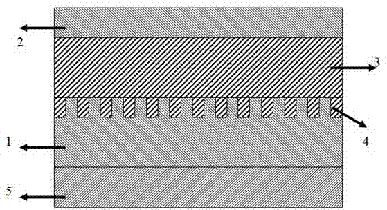
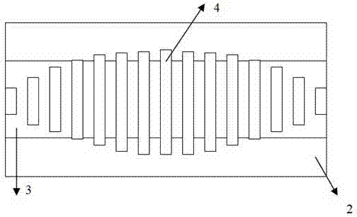
[0029] like figure 1 and figure 2 As shown, a wrinkled apodized waveguide Bragg grating filter of the present invention includes a substrate 5, a lower cladding layer 1, an upper cladding layer 2, a straight waveguide 3 and a lower grating 4 composed of grating lines. The total length of the waveguide grating composed of the straight waveguide 3 and the lower grating 4 is generally on the order of millimeters or centimeters, and the period of the grating in the lower grating 4 is generally several hundred nanometers. The lower cladding layer 1 is fixedly connected to the upper surface of the substrate 5, the lower grating 4 is fixedly connected to the surface of the straight waveguide 3, the bottom surface of the straight waveguide 3 is connected to the top surface of the lower cladding layer 1, and the top surface of the straight waveguid...


PUM


Abstract

The invention provides a wrinkle type apodization waveguide Bragg grating filter, comprising a substrate, a lower cladding layer, an upper cladding layer, a straight waveguide and a lower grating. The width of the lower grating is gradually increased according to a bell-shaped envelope function; the width of a grating wire located at an end part is less than the width of the straight waveguide; and the width of the grating wire located at a middle part is more than the width of the straight waveguide. The invention further provides a manufacturing method of the filter, comprising the following steps of: coating the lower cladding layer on the substrate; manufacturing an anti-etching layer; spinning negative photoresist; carrying out mask exposure; generating a structure of the lower grating through interference; developing and corroding an area of the lower grating; etching the lower grating; removing the residual negative photoresist and corroding; spinning a coating core layer material; evaporating an aluminum layer; etching the straight waveguide; developing an area outside the straight waveguide, and manufacturing the straight waveguide through corrosion; rotatably coating the upper cladding layer, and curing and drying in a vacuum manner. The filter has apodization effects with high reflectivity and high side-mode suppression ratio.

Description

technical field [0001] The invention relates to a Bragg grating filter and a preparation method thereof, in particular to a wrinkled apodized waveguide Bragg grating filter and a preparation method thereof. Background technique [0002] The waveguide grating filter is a key device in the wavelength division multiplexing system, and has been widely used in waveguide input and output couplers, beam splitters, filters, and sensors. Organic polymers have gradually become important materials in integrated optics due to their advantages such as low transmission loss, high stability and reliability, good compatibility, low cost, and easy integration. The use of organic polymer materials allows greater flexibility in device design and fabrication. [0003] The integrated waveguide Bragg grating filter mainly includes a substrate, a lower cladding layer, an upper cladding layer, a straight waveguide, and a lower grating. The lower cladding layer is fixedly connected to the upper su...

Claims


Application Information

Patent Timeline
Patent Type & Authority Patents(China)
IPC IPC(8): G02B6/34G02B6/02G02B6/13
Inventor 胡国华闫以建恽斌峰钟嫄崔一平
Owner SOUTHEAST UNIV
Why Eureka
Try Eureka