
Organic electroluminescent element and novel alcohol-soluble phosphorescent material

An electroluminescence element and luminescence technology, applied in the direction of electroluminescence light sources, luminescent materials, electrical components, etc., can solve the problems of necessary large-scale equipment, difficulty in precise adjustment of vapor deposition speed, and poor productivity

Active Publication Date: 2012-09-12
DAIDEN CO LTD
View PDF10 Cites 23 Cited by
  • Summary
  • Abstract
  • Description
  • Claims
  • Application Information

AI Technical Summary

Problems solved by technology

In addition, in these inventions, since the electron transport layer and the electron injection layer are formed by the vacuum vapor deposition method, large-scale equipment is required, and it is difficult to precisely adjust the vapor deposition rate when vapor deposition of two or more materials at the same time, and there is also a problem of poor productivity.

Method used


Image

  • Organic electroluminescent element and novel alcohol-soluble phosphorescent material
  • Organic electroluminescent element and novel alcohol-soluble phosphorescent material
  • Organic electroluminescent element and novel alcohol-soluble phosphorescent material

Examples


preparation example Construction

[0148] In the preparation of the composition for forming an organic electron transport material, the solutions of the respective raw materials prepared separately may be mixed. At this time, the solvents used for the respective solutions may be the same, but may be different from each other as long as a uniform solution can be obtained. Thereby, a solution can be prepared even when the solubility of the phosphine oxide derivative and the metal compound are greatly different and it is difficult to mix them in a desired quantitative ratio. Furthermore, in any one of the above methods for preparing liquid materials, mixing may also be performed so that the ratio of the host material, the guest material, and the metal salt or metal compound is a desired value. Furthermore, the content of the guest material is preferably 1 to 25% by weight relative to the host material, and the content of the metal salt or metal compound is preferably 1 to 50% by weight relative to the host materia...

Embodiment

[0235] Hereinafter, examples performed for confirming the effects of the present invention will be described.

[0236] Synthesis of host materials

[0237] The host materials used (phosphine oxide derivatives: derivatives represented by the above formulas A to Q) were synthesized according to the method described in the pamphlet of International Publication No. 2005 / 104628.

[0238] Synthesis of guest materials

[0239] [I][bis(2-phenylpyridine-N, C 2’ )-mono(2-(4-diphenylphosphorylphenyl)pyridine-N, C 2’ )] iridium(III)(Ir(ppy) 2 (pdppy)) synthesis

[0240] (I-1) Synthesis of 4-bromophenyldiphenylphosphine oxide (pBrdppo)

[0241] [chemical formula 45]

[0242]

[0243] 5 mL of THF was added to 2.16 g (88.9 mmol) of magnesium, and a THF solution of 22 g (93.2 mmol) of 1,4-dibromobenzene was added dropwise at 0°C. Stirring was performed until magnesium disappeared, 40 mL of THF was added, and further stirring was performed for 1 hour. After cooling to 0°C, 15.7 mL (...


PUM


Abstract

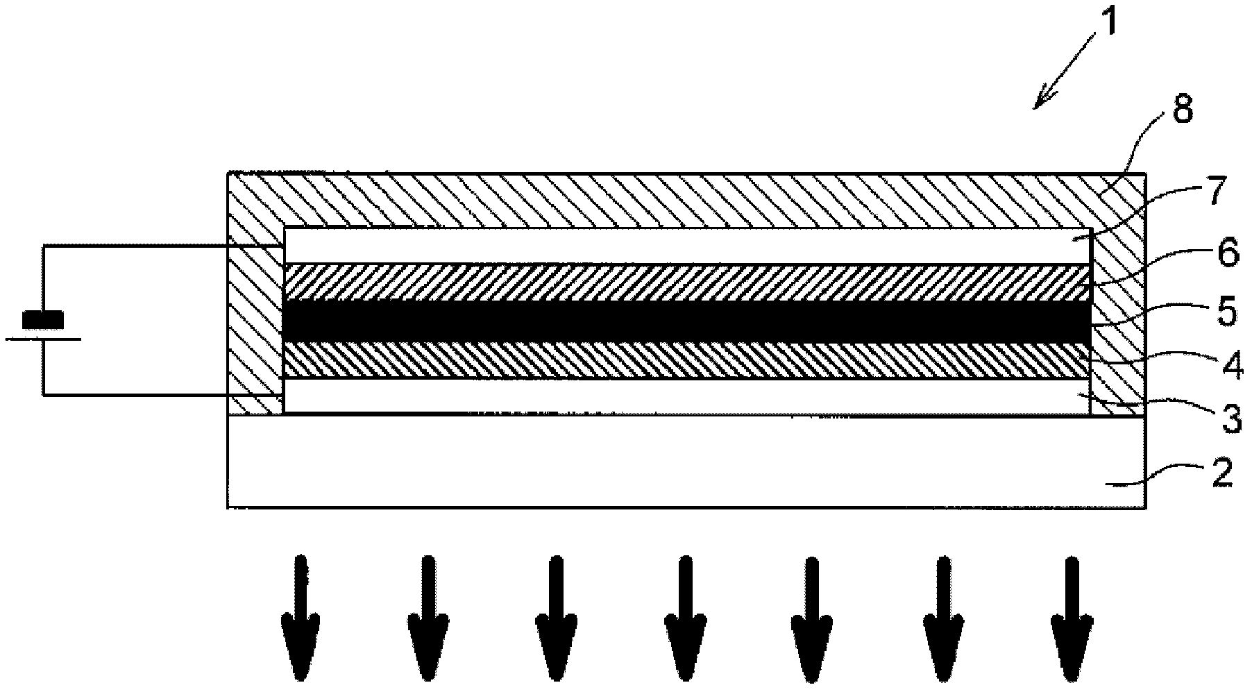
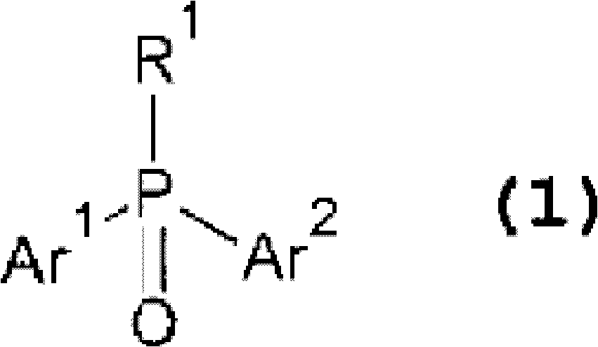
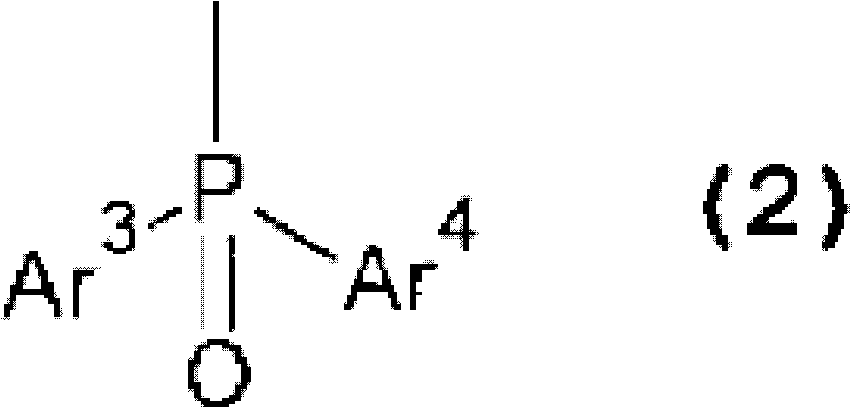
Provided is an organic electroluminescent element having a light-emitting layer that can be formed by a wet process and has excellent electron-injection properties, electron-transport properties, endurance, and luminous efficacy. Also provided is a novel alcohol-soluble phosphorescent material suitable for use in the manufacture of the aforementioned organic electroluminescent element. The provided organic electroluminescent element (1) has a plurality of organic-compound layers (4, 5, 6) laminated between an anode (3) and a cathode (7). A hole-transport layer (5) comprises an organic compound that is insoluble in alcohol-based solvents. A light-emitting layer (6), which is formed by a wet process so as to contact the hole-transport layer (5) on the side thereof that faces the cathode (7), contains: a host material comprising a phosphine oxide derivative that is soluble in alcohol-based solvents; and a guest material that is soluble in alcohol-based solvents and can emit light upon electrical excitation.

Description

technical field [0001] The present invention relates to an organic electroluminescent element and a novel alcohol-soluble phosphorescent luminescent material, and more specifically relates to an organic electronic element having a multilayer structure that can be formed by a wet method and has electron injection properties and electron transport properties. An organic electroluminescent element with a light-emitting layer excellent in characteristics, durability, and luminous efficiency, and a novel alcohol-soluble phosphorescent light-emitting material that can be applied to its manufacture. Background technique [0002] An organic electroluminescence (EL) element (hereinafter referred to as an "organic EL element") in which a light-emitting organic layer (organic electroluminescent layer) is provided between the anode and the cathode has the advantage of being able to operate at low direct current compared to an inorganic EL element. Due to the advantages of low-voltage dr...

Claims


Application Information

Patent Timeline
Patent Type & Authority Applications(China)
IPC IPC(8): H01L51/50C09K11/06
CPCC09K11/06C09K2211/1007C09K2211/1014C09K2211/1029C09K2211/1044C09K2211/185H05B33/14C07F15/0033H10K71/12H10K85/146H10K85/1135H10K85/342H10K50/11H10K2101/10H10K2102/103H10K71/00
Inventor 纳户光治坂井由美柿木泉后藤康之
Owner DAIDEN CO LTD
Learn More