
Method and device for polishing small-bore optical element

A technology for optical components and polishing devices, applied in the direction of polishing compositions containing abrasives, etc., can solve the problems of difficult access of polishing tools, narrow processing space, low shear stress, etc., to achieve enhanced material removal rate, increased contact opportunities, The effect of improving mobility

Inactive Publication Date: 2012-09-19
HUNAN UNIV
View PDF7 Cites 32 Cited by
  • Summary
  • Abstract
  • Description
  • Claims
  • Application Information

AI Technical Summary

Problems solved by technology

However, the electrorheological or magnetorheological polishing brushes with the above-mentioned fine structure have relatively weak removal ability to the workpiece material, and there are dead angles that are difficult to process, and the rheological fluid has low shear stress due to poor fluidity in the micro channel, and the to the problem of low efficiency
[0003] To sum up, although the traditional ultra-precision polishing method for small-diameter axisymmetric rotating curved lenses and micro-molds has been improved and improved, the following problems still exist: 1) The processing space is narrow, and it is difficult for ordinary polishing tools to enter , especially for small and complex curved surfaces, high-steep concave optical components and their molds, etc.
2) The polishing precision is not high
Whether it is using an elastic polishing head or manually polishing axisymmetric rotating surface and other shapes, the surface roughness can be improved, but the surface quality is difficult to ensure uniformity, and it is easy to leave a damaged layer on the surface of the workpiece
3) Low polishing efficiency

Method used


Image

  • Method and device for polishing small-bore optical element
  • Method and device for polishing small-bore optical element
  • Method and device for polishing small-bore optical element

Examples


Embodiment 1

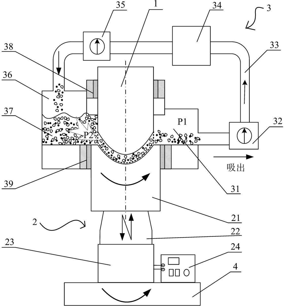
[0040] A small-caliber optical element polishing device, such as figure 1 As shown, it includes a micro polishing groove 14 formed by an axisymmetric rotating curved surface workpiece 21 and the concave surface of the restrictor block 1, a negative pressure groove 31, a suction pump 32, a circulation pipeline 33, a liquid reservoir 34, a press pump 35, a high pressure The groove 36, the upper sealing device 38 and the lower sealing device constitute the entire micro-abrasive fluid circulation system 3; the ultrasonic vibration system 2 is fixedly connected with the rotating platform 4; the bottom of the axisymmetric rotating curved surface workpiece 21 is installed on the horn 22 to vibrate up and down, The upper end of the axisymmetric rotating curved surface workpiece 21 is connected with the high pressure groove 36 and the negative pressure groove 31 through the lower sealing device 39, and the sealing effect is maintained during the working rotation and vibration; the flow ...

Embodiment 2

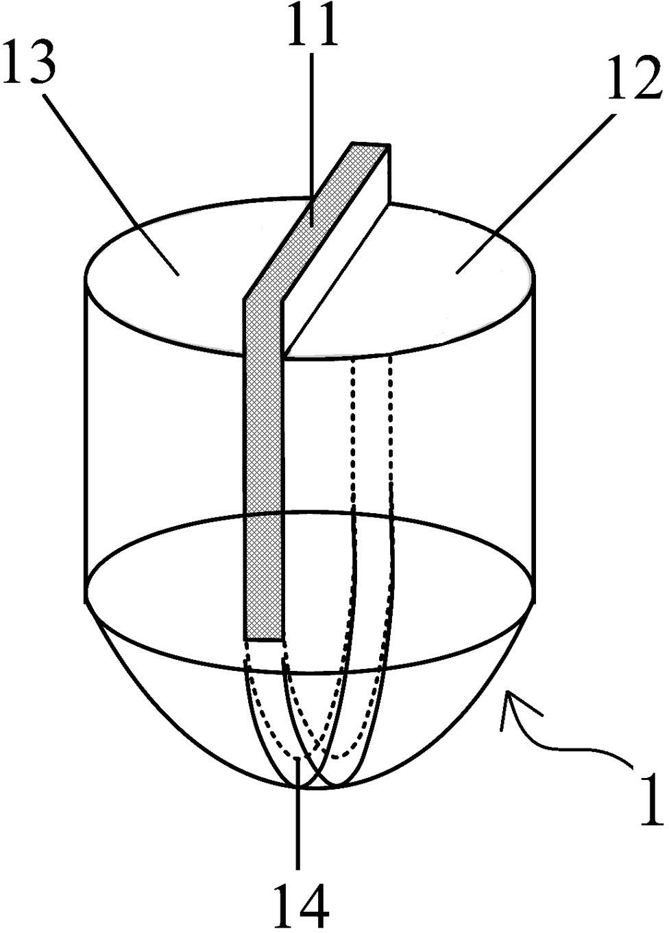
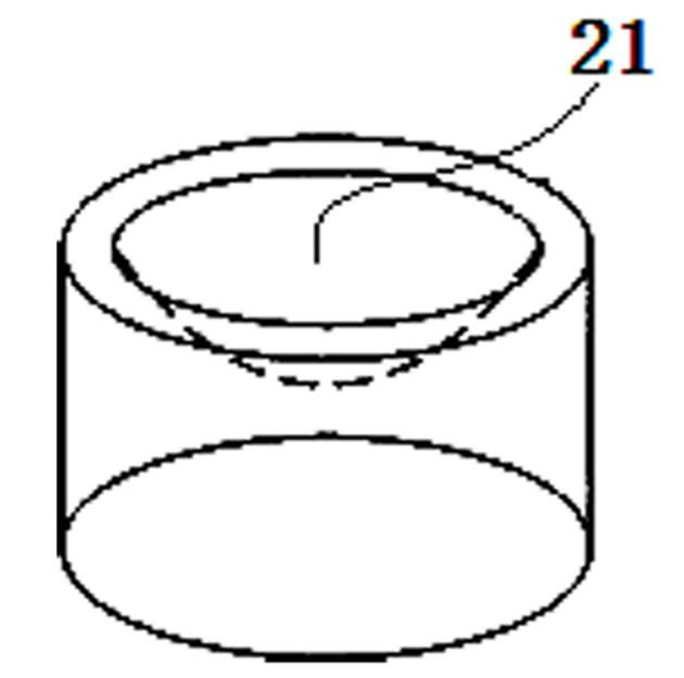
[0049] A small-caliber optical element polishing device, see attached Figure 4 , in this embodiment, the small-diameter axisymmetric rotating convex workpiece 21 is fixed on the horn 22 of the ultrasonic system 2 with a fixture, and the concave adjustment in the axisymmetric rotating convex surface of the workpiece and the flow limiting block 1 with the groove path is adjusted. The gap between the plates 11 is in the range of 0.3mm-1mm, the concave surface of the front stopper 12 and the rear stopper 13 in the restrictor 1 matches the convex shape of the axisymmetric rotational surface to be processed, so that the adjustment plate 11 A tiny polishing groove 14 is formed in the middle of the axisymmetric rotating curved surface; the device structure and processing method of other parts are the same as those in Embodiment 1.


PUM


Abstract

The invention discloses a method and a device for polishing a small-bore optical element, and belongs to the technical field of ultraprecise optical polishing. A throttling block of which the shape is matched with that of a surface to be machined and which is provided with a slot way is fixed on the upper part of the surface to be machined of a workpiece; the workpiece rotates around the own rotating shaft; a flexibly cyclic polishing belt is formed on the slot way by using fine abrasive particle fluid and machines the surface of the workpiece. By using pressure difference and a mode of fluid suction, the fluidity and sliding friction property of the fine abrasive particle fluid is enhanced; by adoption of ultrasonic vibration of an axisymmetric rotating curved-surface workpiece, the impact effect and cutting effect of fine abrasive particles on the workpiece are enhanced, so that the material removal rate is enhanced, the surface with high quality is obtained efficiently, and surface scatheless trace removal is realized. The method and the device are applied to ultraprecise polishing of curved surfaces of various rotationally-symmetrical optical elements and are high in practical value in the aspect of automatic processing.

Description

technical field [0001] The invention belongs to the technical field of ultra-precision optical polishing processing, and relates to a polishing method and device suitable for processing curved surfaces of small-diameter optical elements. Background technique [0002] With the rapid development of optics, electronics, automobiles, aerospace and other disciplines, the demand for micro axisymmetric rotating curved optical lenses in digital cameras, camera phones, car camera devices, endoscopes, weapon aiming systems and other products has increased sharply. The quality requirements of its processed surface are becoming more and more stringent. High-quality tiny axisymmetric rotational curved mirrors and their molds require nanoscale surface roughness and extremely low subsurface damage. Beijing Institute of Technology has developed a DC pulsed double-electrode grinding and polishing method for small-caliber optical surface processing, and Hunan University has developed a magne...

Claims


Application Information

Patent Timeline
Patent Type & Authority Applications(China)
IPC IPC(8): B24B1/04C09G1/02
Inventor 陈逢军
Owner HUNAN UNIV
Learn More