Electric vacuum servo brake control system of pure electric automobile

A pure electric vehicle, vacuum boost technology, applied in the direction of brake transmission, brakes, vehicle components, etc., can solve the problems of poor braking effect, hidden dangers, vehicle performance and driving safety restrictions, etc., to ensure sensitivity and reliability, The effect of ensuring driving safety

Inactive Publication Date: 2012-09-19
SHENZHEN GREENWHEEL ELECTRIC VEHICLE CO LTD
View PDF4 Cites 4 Cited by
  • Summary
  • Abstract
  • Description
  • Claims
  • Application Information

AI Technical Summary

Problems solved by technology

In the current pure electric vehicles, the engine is replaced by the electric motor, and the electric motor cannot keep rotating like the engine, so the...

Method used


Image

  • Electric vacuum servo brake control system of pure electric automobile
  • Electric vacuum servo brake control system of pure electric automobile
  • Electric vacuum servo brake control system of pure electric automobile

Examples


Embodiment 1

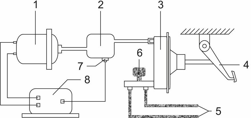
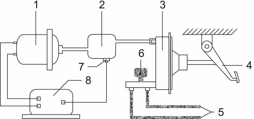
[0050] Such as figure 1 The pure electric vehicle brake booster control system includes: 1 vacuum pump, 2 vacuum air storage tank, 3 booster master cylinder assembly, 4 brake pedal, 5 brake oil circuit, 6 oil storage tank, 7 pressure sensor, 8 vacuum booster Brake controls. The booster master cylinder assembly 3 and the brake pedal 4 form a link mechanism, which is used to provide boost for the brake pedal 5. The booster master cylinder assembly 3 is connected to the vacuum air storage tank 2 by a vacuum pipeline, and the vacuum air storage tank 2 and then connected to the vacuum pump 1 via the vacuum pipeline, the vacuum air storage tank 2 is provided with a pressure sensor 7, the brake vacuum booster controller 8 is electrically connected with the pressure sensor 7 and the vacuum pump 1, and is used to detect the vacuum air storage tank 2 through the pressure sensor 7 The size of the vacuum pressure value, and then through the brake vacuum booster controller 8 to control th...

Embodiment 2

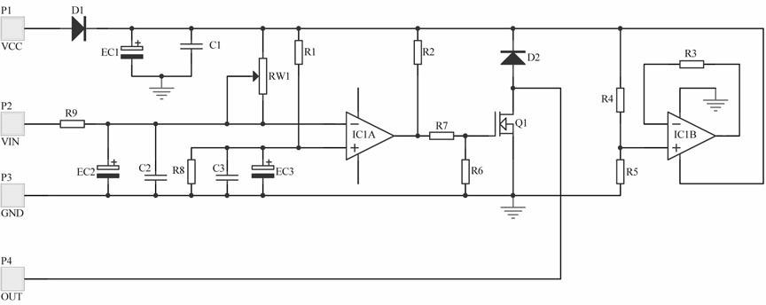
[0053] Such as figure 2 It is a schematic diagram of the principle of the vacuum booster brake control device provided by the present invention.

[0054] figure 2 R1, R2, R3, R3, R4, R5, R6, R7, R8, R9 represent resistors, C1, C2, C3 represent capacitors, EC1, EC2, EC3 represent electrolytic capacitors, RW1 represent adjustable resistors, D1, D2 Represents a diode, Q1 represents a MOS transistor, IC1A and IC1B represent a comparator, VCC represents a power input terminal, VIN represents a signal input terminal, GND represents a ground terminal, and OUT represents an output terminal.

[0055] As shown in the figure, the hardware control circuit includes, D1, EC1, C1 composed of power supply reverse connection protection and power filtering, R1, R8, EC3, C3 provide the comparison voltage threshold of comparator IC1A, the voltage threshold range can be It is set according to the specific situation. Preferably, the voltage threshold is half of the power supply voltage, and the...


PUM


Abstract

The invention relates to an electric vacuum servo brake control system of a pure electric automobile. The electric vacuum servo brake control system comprises a vacuum pump, a vacuum gas storage tank, a booster main cylinder assembly, a braking pedal, a brake oil path, an oil storage tank, a pressure sensor and a vacuum servo brake control device, wherein the pressure sensor is located on the vacuum gas storage tank; a connecting rod mechanism is formed by the booster main cylinder assembly and the braking pedal; the booster main cylinder assembly is communicated with the vacuum gas storage tank through a vacuum pipeline; the vacuum gas storage tank is communicated with the vacuum pump through the vacuum pipeline; and the vacuum servo brake control device is electrically connected with the vacuum pump and the pressure sensor to control the opening and the closing of the vacuum pump. According to the invention, a brake servo control device is used for controlling the opening and the closing of the vacuum pump, so as to guarantee a vacuum pressure of the vacuum gas storage tank in a brake vacuum servo control system, effectively guarantee the flexibility and the reliability of a brake vacuum servo device of the pure electric automobile, and guarantee the driving safety to the greatest extent.

Description

technical field [0001] The invention relates to an automobile brake system, in particular to a special braking vacuum booster control system for a pure electric automobile. technical background [0002] At present, automobiles are basically equipped with brake boosters, especially the use of brake vacuum boosters is very popular. Its principle is to use the pressure difference between the negative pressure generated when the engine is working and the atmospheric pressure to force the rubber diaphragm in the main brake assembly of the brake booster to move and push the piston of the brake master cylinder, so as to reduce the pressure of people stepping on the brake pedal. strength and reliability. [0003] Traditional fuel vehicles mainly use the mechanical rotation of the engine to continuously pump the vacuum to ensure a certain amount of brake power, and the operation method is more sensitive. In the current pure electric vehicles, the engine is replaced by the electric ...

Claims


Application Information

Patent Timeline
IPC IPC(8): B60T13/72B60T13/52
Inventor 不公告发明人
Owner SHENZHEN GREENWHEEL ELECTRIC VEHICLE CO LTD
Why Eureka
Try Eureka