Injection mixing pump

A technology of injection mixing and mixing tubes, which is applied in the direction of injection pumps, pumps, non-volume pumps, etc., and can solve the problems of inappropriate high-efficiency injection mixing pumps, large axial dimensions of injectors, and unfavorable installation and use.

Inactive Publication Date: 2012-09-19
韩铁夫
View PDF9 Cites 5 Cited by
  • Summary
  • Abstract
  • Description
  • Claims
  • Application Information

AI Technical Summary

Problems solved by technology

[0007] The existing jet mixing pump mainly relies on the turbulent diffusion of the jet in the long stroke of the mixing tube to mix the primary fluid and the secondary fluid; the turbulent diffusion of the jet requires a process of development and strengthening in the mixing tube , so the injector must have a slender mixing tube (or mixing diffuser tube), and a large-flow injector needs a large-dia

Method used


Image

  • Injection mixing pump
  • Injection mixing pump
  • Injection mixing pump

Examples


Embodiment 1

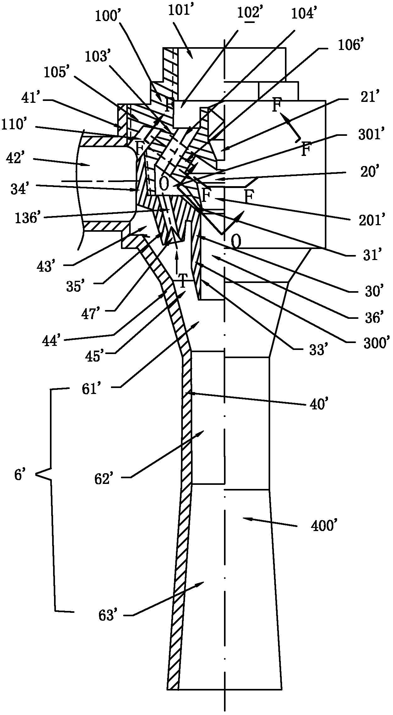
[0043] see figure 1 , the present embodiment is a jet mixing pump that injects a secondary fluid with a primary fluid and outputs a mixed fluid. The jet mixing pump is coaxially provided with an inner ring injector, an outer ring ejector and a total mixing output pipe 6' along the central axis; the inner ring injector is fixed in the outer ring ejector, and the total mixing output pipe 6' Fixed at the end of the outer ring ejector. The outlet end of the inner ring ejector and the outlet end of the outer ring ejector are smooth and straight through the total mixing output pipe 6' to form an outlet jet mixer.

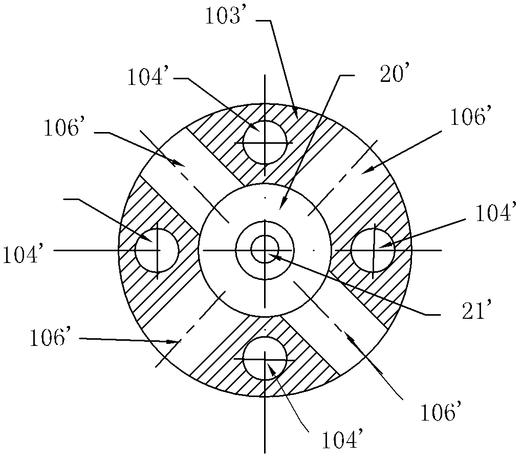
[0044] The inner ring injector is formed by butting the main fluid assembly 100', the central nozzle 21' and the inner pipe assembly 300' concentrically. A main fluid inlet pipe 101' is arranged at the center of the inlet end of the main fluid assembly 100', a tubular central nozzle 21' is arranged in the central outlet hole of the main fluid inlet pipe 101', and an out...

Embodiment 2

[0055] see Figure 7 , present embodiment is to use a kind of main fluid that imports from main fluid inlet pipe 11, introduces respectively from the first time fluid inlet 12 and the second time fluid inlet pipe 42 input two kinds of secondary fluids, from total mixing outlet pipe 6 Jet mixing pumps that output mixed fluids are especially suitable for applications where the primary fluid is liquid or liquid plus gas, and the secondary fluid is gas. The jet mixing pump is coaxially provided with an inner ring injector, an outer ring ejector and a total mixing output pipe 6 along the central axis; the inner ring injector is fixed in the outer ring ejector, and the total mixing output pipe 6 is fixed at the end of the outer ring ejector. The outlet end of the inner ring ejector and the outlet end of the outer ring ejector are smooth and straight through the total mixing output pipe 6 to form an outlet jet mixer.

[0056] The inner ring injector is formed by butting the main fl...


PUM


Abstract

The invention relates to a mixed flow injection device, in particular to an injection mixing pump. The injection mixing pump is concentrically provided with an inner ring injector, an outer ring ejector and an overall mixing output pipe along a central axis; the inner ring injector is fixedly arranged in the outer ring ejector; the inner ring injector is sequentially provided with a central main fluid inlet pipe, a central nozzle, a central mixing chamber and a center mixing pipe along the central axis, wherein the central main fluid inlet pipe is arranged at the inlet end of the inner ring injector; the periphery of the central mixing chamber is communicated with an inlet of a first fluid; the outer ring ejector is sequentially provided with a main fluid ring cavity, an outer ring nozzle, a ring mixing chamber and a ring mixing pipe along the central axis; the periphery of the ring mixing chamber is communicated with a second fluid; and the outlet end of the inner ring injector and a flat straight-through overall mixing output pipe at the outlet end of the outer ring ejector form an outlet injection mixer. The injection mixing pump provided by the invention is light in weight, has small axial dimension and high injection rate, shows good performance in large flow and can obtain high output pressure.

Description

technical field [0001] The invention relates to a mixed flow injection device, in particular to an injection mixing pump for mixed fluid injection. Background technique [0002] The jet mixing pump is also called jet pump, which is a device that injects low pressure (or no pressure) secondary fluid with high pressure primary fluid, and completes primary fluid suction secondary fluid for medium pressure mixed flow delivery. Since the jet mixing pump has no moving parts, it is reliable and widely used in fluid equipment in various fields. [0003] The existing typical Venturi injector is actually a jet mixing pump, which consists of a main fluid inlet pipe, a nozzle, a secondary fluid inlet, a mixing chamber, a throat or a mixing diffuser. The secondary fluid passed into the mixing chamber is sucked into the mixing tube by the jet of the primary fluid nozzle, and the primary and secondary fluid is output from the mixing diffuser tube after being mixed and equalized. Such inj...

Claims


Application Information

Patent Timeline
IPC IPC(8): F04F5/00
Inventor 韩铁夫
Owner 韩铁夫
Why Eureka
Try Eureka